Maintenance
306
S3300 Smart Managed Pro Switch
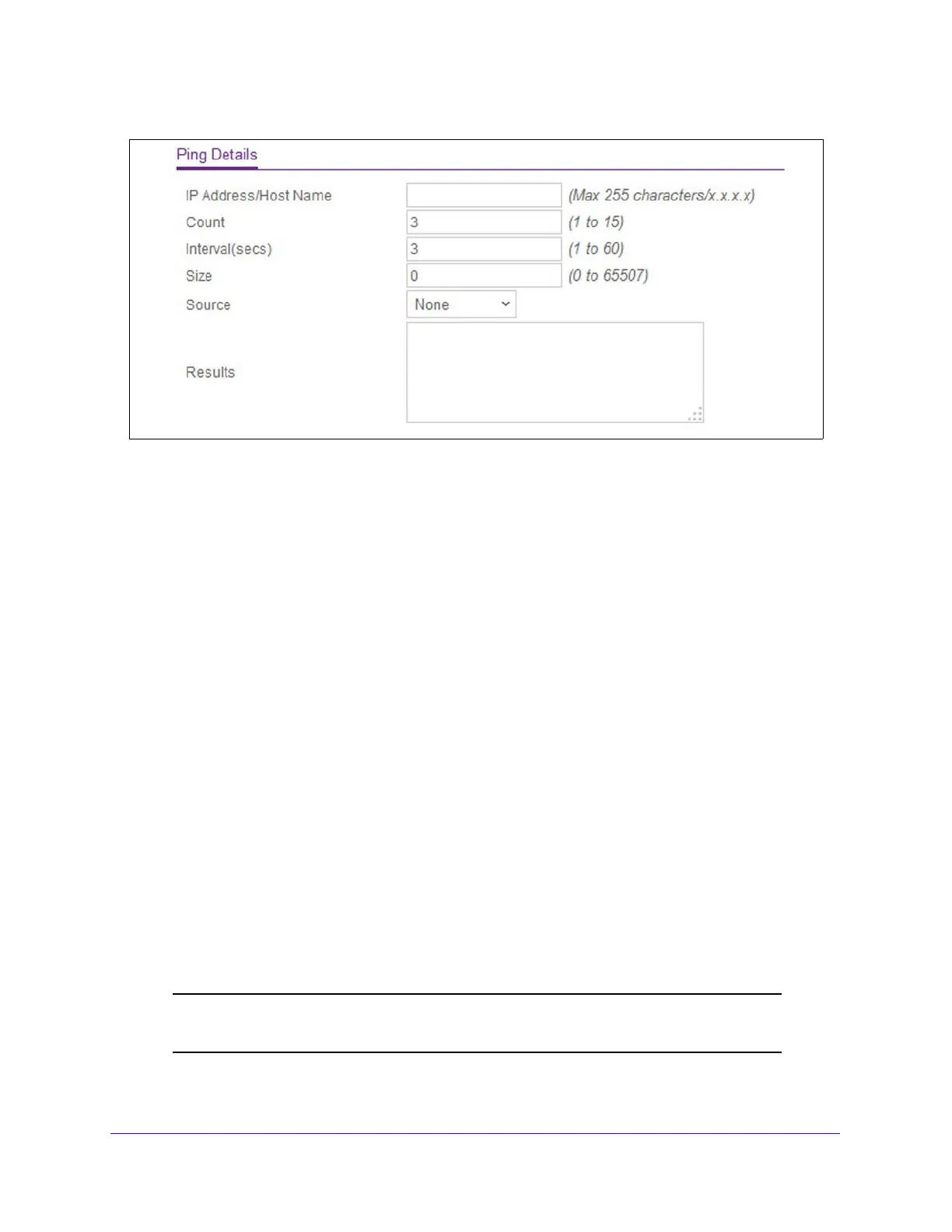
Figure 111. Ping IPv4
2. In the IP Address/Host Name field, specify the IP address or Hostname of the station you
want the switch to ping. The initial value is blank. The IP Address or Hostname you enter is
not retained across a power cycle.
3. Option
ally, configure the following settings:
• In the
Count field, specify the number of pings to send. The default value is 3. The
range is 1 to 15. The Count you enter is not retained across a power cycle.
• In the
Interval field, specify the number of seconds between pings sent. The default
value is 3 seconds. The range is 1 to 60. The Interval you enter is not retained across
a power cycle.
• In the
Size field, specify the datagram size of the ping (ICMP) packet to send. The
default value is 0 bytes. The range is 0 to 65507. The Size you enter is not retained
across a power cycle.
4. In
the Source field, select the source type from which the ping is sent, which is one of the
following:
• None — The source is the IP address of the default outgoing interface. If source is not
re
quired, select None as the source option.
• IP Address — The source is an IP address that you specify
. If you select this option,
the IP Address field appears. Specify the source IP address of the ping in the IP
address field.
• Interface — The ping is sent from a specified inte
rface to use when sending the Echo
request packets. If you select this source option, the Interface field is shown. Use the
menu to select the interface from which to send the ping.
Note: Values configured in the fields above are not saved to the switch. As a
result, refreshing the page sets these fields to the default values.
 Loading...