Expansion Power Supplies Overview
178 AFP-200 PN 15511:H2 10/14/2002
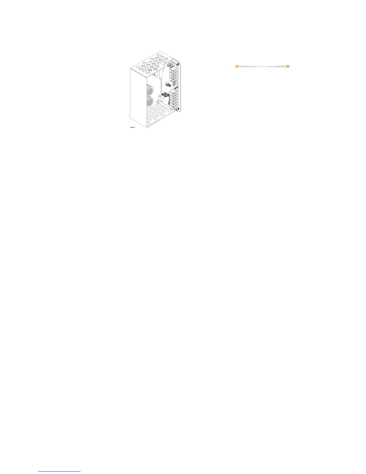
continuous). The APS-6R mounts in the bottom of the AFP-200 cabinet. Figure 159
shows an APS-6R and the supplied Power Cable:
Figure 159 APS-6R Auxiliary Power Supply
Electrical Specifications
AC primary input power (TB1) Wire Size: #14 AWG with 600 VAC insulation
120 VAC, 60 Hz, 2.5 A
240 VAC, 50 Hz, 1.2 A
24 VDC Secondary input power (lead-acid batteries only)
TB3-1 (+) 25 mA DC standby current
TB3-2 (–) 16 mA DC standby current (with AC fail delay
operating)
24 VDC output power (TB2) Total 6 A (4 A continuous)
Circuit 1 (TB2-1, TB2-2; or J1) 3 A @24 VDC power-limited (+10, –15%)
Circuit 2 (TB2-3, TB2-4; or J2) 3 A @24 VDC power-limited (+10, –15%)
Fuses
F1 (AC supervision) 250 VAC, 4A, 3 AG, slow blow
F2 (battery supervision) 32 VAC, 10 A, 3 AG, slow blow
Trouble supervision bus
J3 output Form A contact (open collector)
J4 input Form A contact (open collector)
Note: J3 and J4 can be interchanged.
Loss of AC Indication
Immediate indication (default)
8 hour delay (cut JP2)
16 hour delay (cut JP2 and JP3)
Size of APS-6R in enclosure
6.09 in. x 4.23 in. x 2.92 in.
Power Cable (71093)
Technical Manuals Online! - http://www.tech-man.com
 Loading...


