Wiring a Signaling Line Circuit (SLC) Installation
AFP-200 PN 15511:H2 10/14/2002 55
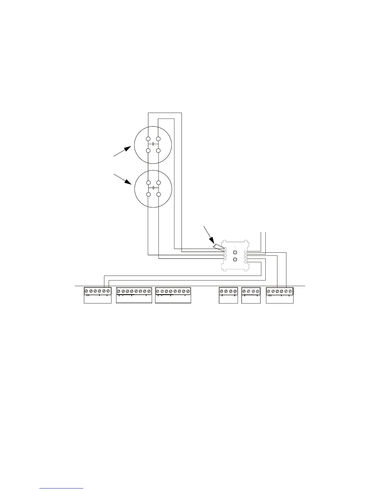
Wring an NFPA Style D IDC with FZM-1 Modules
Note: Figure 37 shows typical wiring for a supervised and power-limited NFPA Style D
(Class A) IDC using FZM-1 modules. Refer to Installation Document shipped with
each two-wire detector monitor module for specific installation notes for this variety of
module.
Wiring guidelines for this IDC are:
Refer to the Device
Compatibility Document for
detector and power
supervision relays.
• Maximum Initiating Device Circuit (IDC) resistance is 25 ohms.
• Maximum alarm current is 90 mA.
• Maximum detector standby current is 2.4 mA.
Figure 37 Typical Style D (Class A) IDC Wiring with FZM-1 Modules
TB4
TB5 TB6
TX REF RX REF
OUT O UT IN IN
1 2 3 4 5 6
A B B+ A+ B- A-
TB1
TB2 TB3
+ - + - + -
B+ B- B+ B- B+ B- B+ B- NO C NO NC C NO NC C
- +
+
+
-
-
+
+
-
-
90
81
72
63
54
-
+
+
-
To the next device
on the SLC
24 VDC filtered, low-noise and resettable power:
24 VDC (+) to TB1-5
24 VDC (–) to TB1-6
3.9K ELR –
supplied with
FZM-1 module
Compatible two-wire
smoke detectors
SLC out:
SLC (+) to TB6-3
SLC (–) to TB6-5
CPU
Technical Manuals Online! - http://www.tech-man.com
 Loading...


