Programming How to Enter Program Change
76 AFP-200 PN 15511:H2 10/14/2002
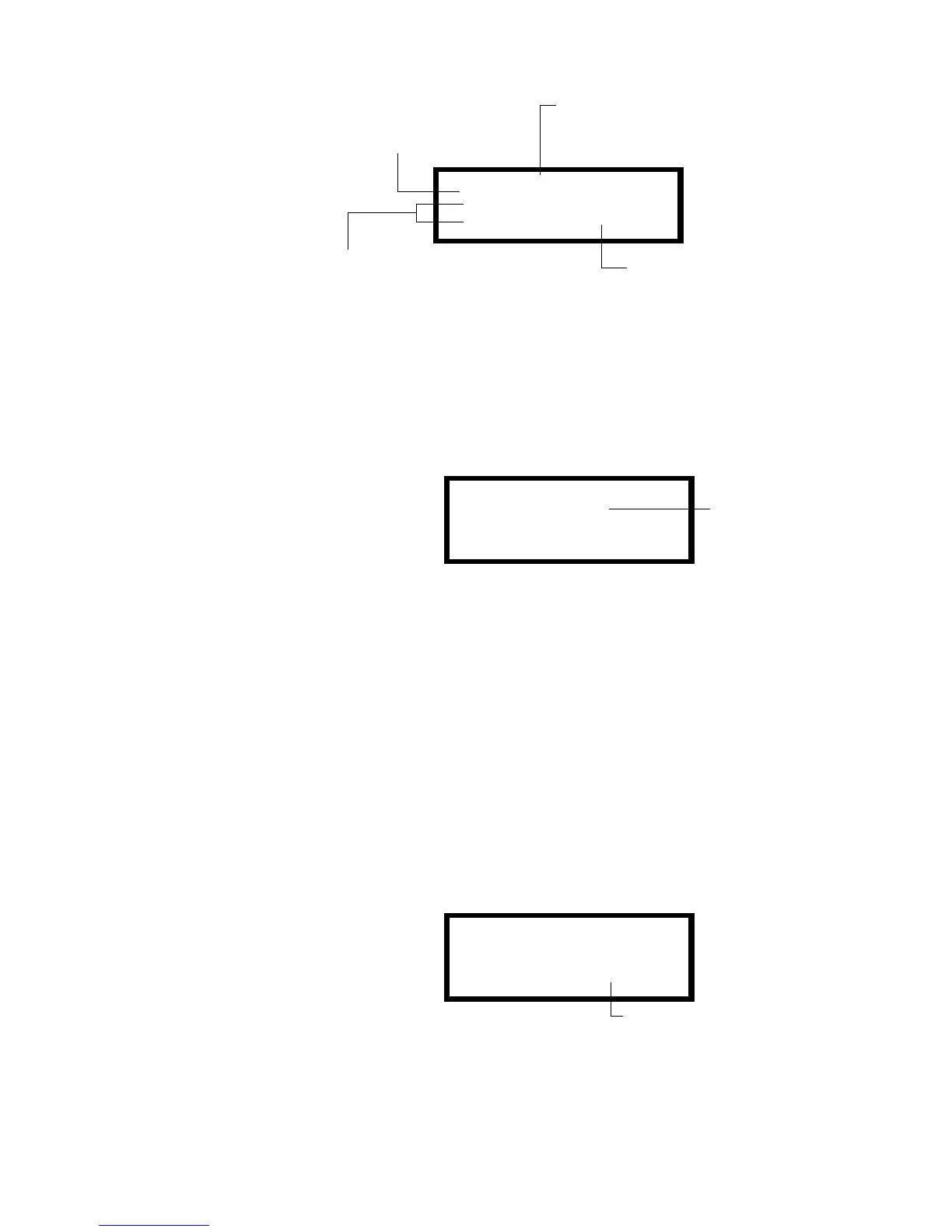
Figure 59 Sample New Device Screen
4. Press the
ENTER key to add detector 04 to the program with the default program
information. If you want to change the default information, use the programming
keys to do so, then press the
ENTER key to add detector 04 to the program. To reject
the new device, press the
BACKSPACE key to return to the Program Change screen.
5. The Autoprogram Summary screen appears. You can verify addition of the detector
to the program by noting the new count of detectors as shown in Figure 60.
Figure 60 Sample Autoprogram Summary Screen
6. Press the
ENTER key, then press the BACKSPACE key to save the program in memory
and return to the Program Change screen (Figure 53 on page 71).
How to Remove a Device from the Program
You can also use the Autoprogram option to remove addressable detectors and modules
from the control panel program.
The following steps describe how to delete a detector at SLC address 04 with
10 detectors in the existing program:
When using the Autoprogram
option with an existing
program, the control panel
does not change program
information for installed and
programmed devices.
1. Disconnect and remove the detector from the SLC at address 04.
2. From the Program Change screen (Figure 53), press the 1 key to start
Autoprogram. The Autoprogram Prompt screen (Figure 56 on page 74) while the
control panel identifies addressable devices connected to the SLC.
3. When finished identifying SLC devices, the control panel displays a screen,
indicating a missing detector at SLC address 04 as shown in Figure 61.
Figure 61 Sample Missing Device Screen
4. Press the
ENTER key to delete detector 04 from the program and return to the
Program Change screen (Figure 53 on page 71).
PROGRM@SMOKE(PHOTO)
DETECTOR@ADDRESS@01
ZO3@Z@@@Z@@@Z@@@Z@@
2.0%@@@@@@*P*@@@@D04
Default Autoprogram information for the device. To
edit this information, refer to “How to Edit or Delete
a Point (2=point)” on page 78 for instructions.
Device address (detector at
SLC address 04 shown)
Type Code for the device which you can only edit
using the Point Programming option. For details,
refer to “How to Edit or Delete a Point (2=point)”
on page 78.
Default label for the device. To
edit, refer to “How to Edit or Delete
a Point (2=point)” on page 78.
DETECTORS :11
MODULES :02
PANEL CKTS :04
Note that the number
of detectors increases
(from 10 to 11) to
show the addition of
the detector.
PROGRM@SMOKE(PHOTO)
FLOOR1@MAIN@LOBBY
DEVICE@NOT@ANSWERING
DELETE@FROM@MEM?@D04
D04 – the address of the device
removed from the SLC.
Technical Manuals Online! - http://www.tech-man.com
 Loading...


