121
Settings Section 3-1
• Connect a two-conductor twisted-pair shielded cable to the Analog Output
Unit.
• Do not install power lines or high-tension lines along in close proximity to
the Analog Output Unit’s output lines.
• The shielded wire must be grounded on the signal reception side.
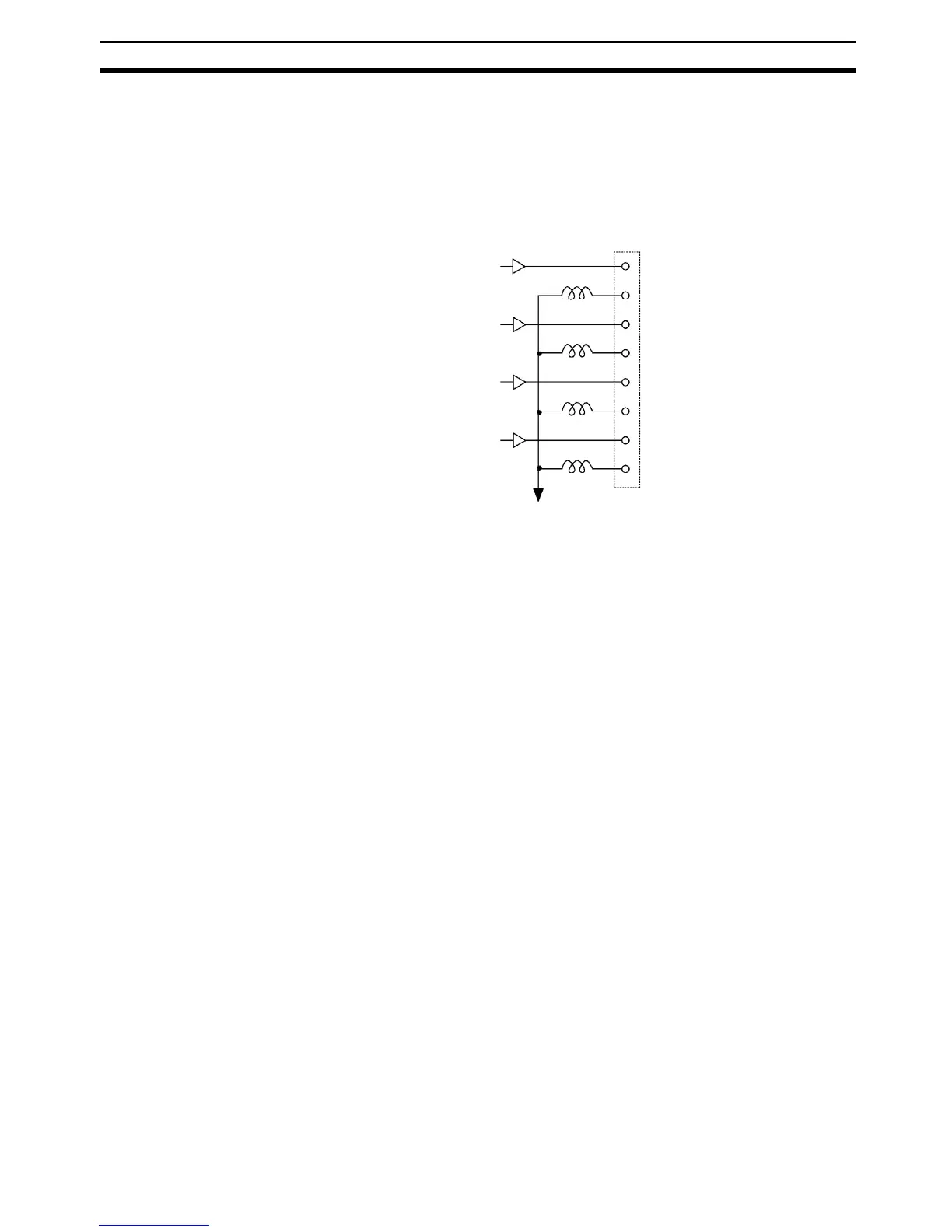
• The negative side of each output lines are internally connected as shown
in the following diagram.
If the CQM1-IPS02 is connected to the Analog Output Unit and Analog Input
Unit, the analog GND terminal of the Analog Output Unit and that of the Ana-
log Input Unit will be connected to each other.
Analog GND
I1+
I1–
V1+
V1–
I2+
I2–
V2+
V2–