Chapter 4: System Installation
PIN 15
PIN 7
PIN 14
PIN 6
PIN 13
PIN 5
PIN 11
PIN 3
PIN 10
PIN 2
PIN 9
PIN 1
PIN 4
PIN 12
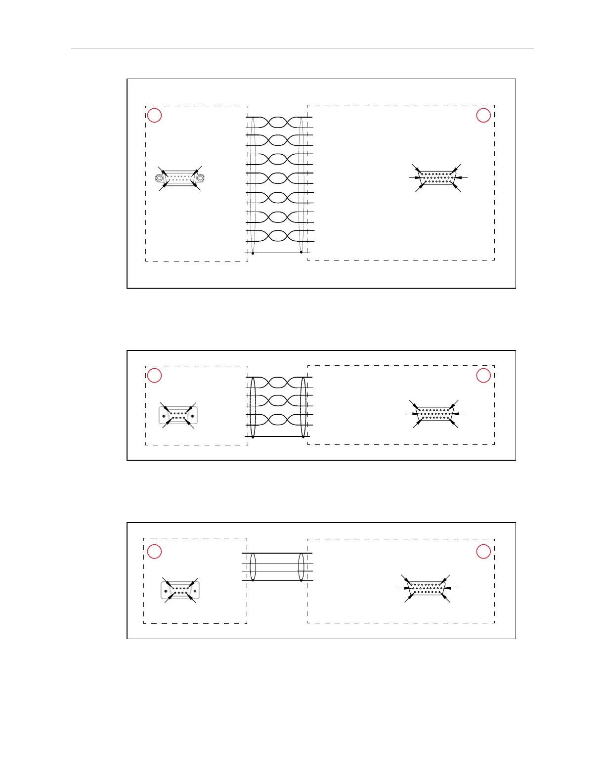
PIN 2 (ENC1_A+)
PIN 3 (ENC1_A-)
PIN 11 (ENC1_B+)
PIN 12 (ENC1_B-)
PIN 19 (ENC1_Z+)
PIN 20 (ENC1_Z-)
PIN 4 (ENC2_A+)
PIN 5 (ENC2_A-)
PIN 13 (ENC2_B+)
PIN 14 (ENC2_B-)
PIN 21 (ENC2_Z+)
PIN 22 (ENC2_Z-)
PIN 1 (5V)
PIN 10 (GND)
PIN 8 PIN 1
PIN 15 PIN 9
C
B
PIN 1
PIN 10
PIN 19
PIN 9
PIN 18
PIN 26
SHIELD
SHIELD
Figure 4-4. eAIBXBELTIOAdapterCable Pinout - Encoder 1 and 2 Connections
NOTE: Cable shields connected to DSUBshell.
PIN 5
PIN 4
PIN 6
PIN 1
PIN 3
PIN 2
PIN 7 (CLK +)
PIN 8 (CLK -)
PIN 6 (EXPIO 5V)
PIN 15 (GND)
PIN 16 (DATA +)
PIN 17 (DATA -)
D
PIN 1 PIN 5
PIN 6
B
PIN 1
PIN 10
PIN 19
PIN 9
PIN 18
PIN 26
PIN 9
SHIELD
SHIELD
Figure 4-5. eAIBXBELTIOAdapterCable Pinout - Force / EXPIO Connections
NOTE: Cable shields connected to DSUBshell.
PIN 3
PIN 2
PIN 5
PIN 25 (TXD)
PIN 26 (RXD)
PIN 18 (GND)
E
B
PIN 1
PIN 10
PIN 19
PIN 9
PIN 18
PIN 26
PIN 1 PIN 5
PIN 6
PIN 9
SHIELD
SHIELD
Figure 4-6. eAIBXBELTIOAdapterCable Pinout - RS232 Connections
NOTE: Cable shields connected to DSUBshell.
14402-000 Rev. F eCobra User's Guide 47