142 eCobra User's Guide 14402-000 Rev. F
7.8 Installing Adjustable Hardstops
7.8 Installing Adjustable Hardstops
We offer an adjustable hardstop kit for Joint 1 and Joint 2 on the eCobra robots. These are user-
installed options that can be used to limit the work envelope of the robot. The part number for
the kit is 02592-000.
Joint 1 Adjustable Hardstops
The Joint 1 Adjustable Hardstops consist of two black rubber stop cylinders, and the required
screws to install them. There are two locations for the hardstops on each side of the robot, Pos-
ition 1 and Position 2. See the following figure.
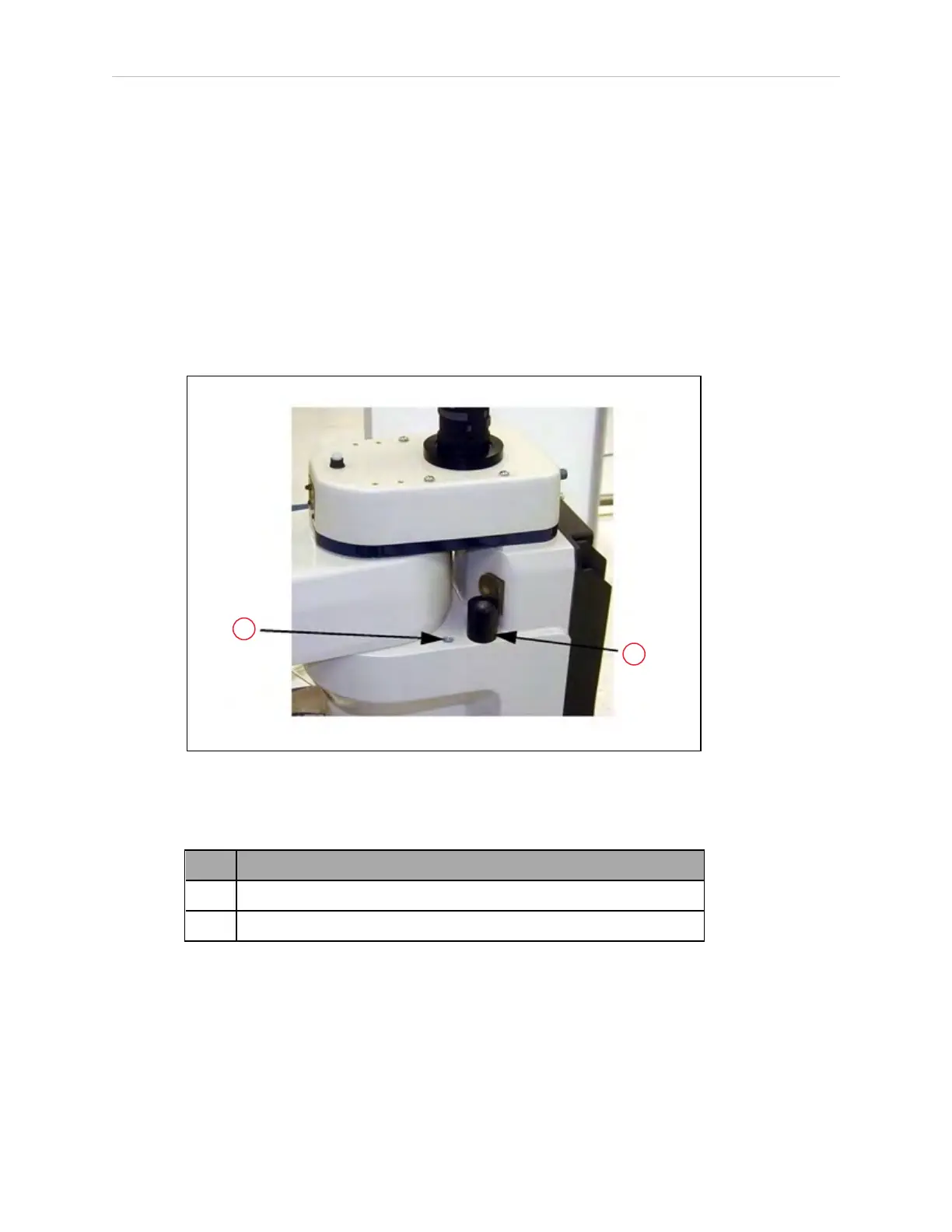
Figure 7-16. Joint 1 Adjustable Hardstops
Table 7-18. Joint 1 Adjustable Hardstop Description
Item Description
1 Location for Position 1
2 Joint 1 Adjustable Hardstop Installed in Position 2
Installation Procedure
1.
Remove the plug from desired threaded hole, Position 1 or 2, on each side of the robot.
2.
Install the adjustable hardstop into the threaded hole using an 8 mm hex wrench.
Tighten to a torque of 5.1 N·m (45 in-lbf).
3.
Repeat the process on the other side of the robot.