Chapter 5: System Operation
robot status panel, as shown in Figure 5-2. When system power is on, pressing this button
releases the brake, which allows movement of Joint 3.
NOTE: 24 Volt robot power must be on to release the brake.
If this button is pressed while high power is on, high power will automatically shut off.
CAUTION: PROPERTYDAMAGERISK
Pressing the Brake Release button may cause the quill and tool flange to fall.
When the Brake Release button is pressed, Joint 3 may drop to the bottom of its
travel. To prevent possible damage to the equipment, make sure that Joint 3 is
supported while releasing the brake and verify that the end-effector or other
installed tooling is clear of all obstructions.
Remote Brake Release Feature
You can also configure the XIO Input 6.2 (pin 18) to act as an alternate hardware brake release
input. The setting is available on the Robot page in the ACE software. The parameter is
Remote Brake Release Input. When enabled (True), activating XIO Input 6.2 is identical to
pressing the brake button on the status display. The input status will still reflect in the IO
register.
If an alternate (user-supplied)brake release button is used, ensure that the brake release button
displays a warning similar to the preceding WARNING. This is to comply with ISO 10218-1,
Clause 5.13.
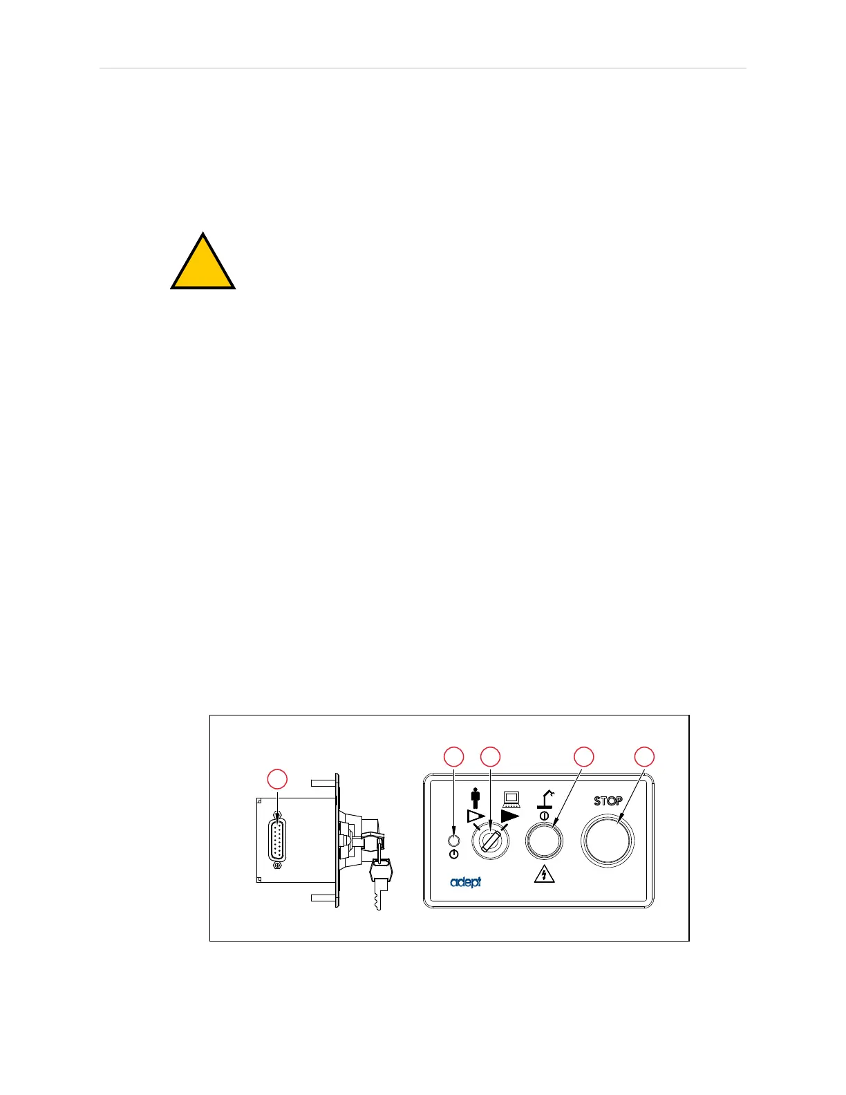
5.4 Front Panel
NOTE: The factory-supplied Front Panel E-Stop is designed in accordance with
the requirements of IEC 60204-1 and ISO 13849.
IMPORTANT: Any user-supplied front panel E-Stop must be designed in accord-
ance with the requirements of IEC 60204-1 and ISO 13849. The push button of
the E-Stop must comply with ISO 13850 (Clause 5.5.2).
Figure 5-3. Front Panel
14402-000 Rev. F eCobra User's Guide 81