Chapter 5: System Operation
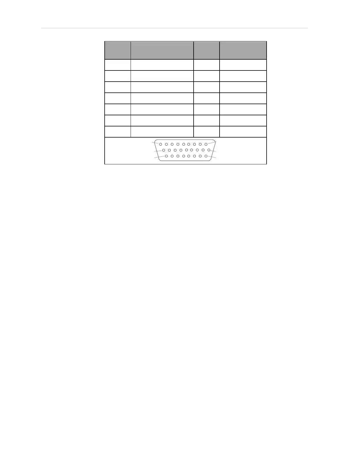
Pin No. Designation
Signal
Bank
eV+ Signal
Number
20 Output 2 0098
21 Output 3 0099
22 Output 4 0100
23 Output 5 0101
24 Output 6 0102
25 Output 7 0103
26 Output 8 0104
Pin 1Pin 9
Pin 10
Pin 18
Pin 26 Pin 19
XIO Input Signals
The 12 input channels are arranged in two banks of six. Each bank is electrically isolated from
the other bank and is optically isolated from the robot’s ground. The six inputs within each
bank share a common source/sink line.
The inputs are accessed through direct connection to the XIO connector (see the previous
table), or through the optional XIO Termination Block. See the documentation supplied with
the termination block for details.
For REACTI programming, high-speed interrupts, or vision triggers:
l
With a SmartController EX, you can only use the EXXDIO inputs.
l
Without a SmartController EX, you can only use the XIO inputs.
See the eV+ Language User’s Guide for information on digital I/O programming.
14402-000 Rev. F eCobra User's Guide 87