Chapter 4: System Installation
This chapter does not cover I/O. Refer to Connecting Digital I/O to the System on page 83.
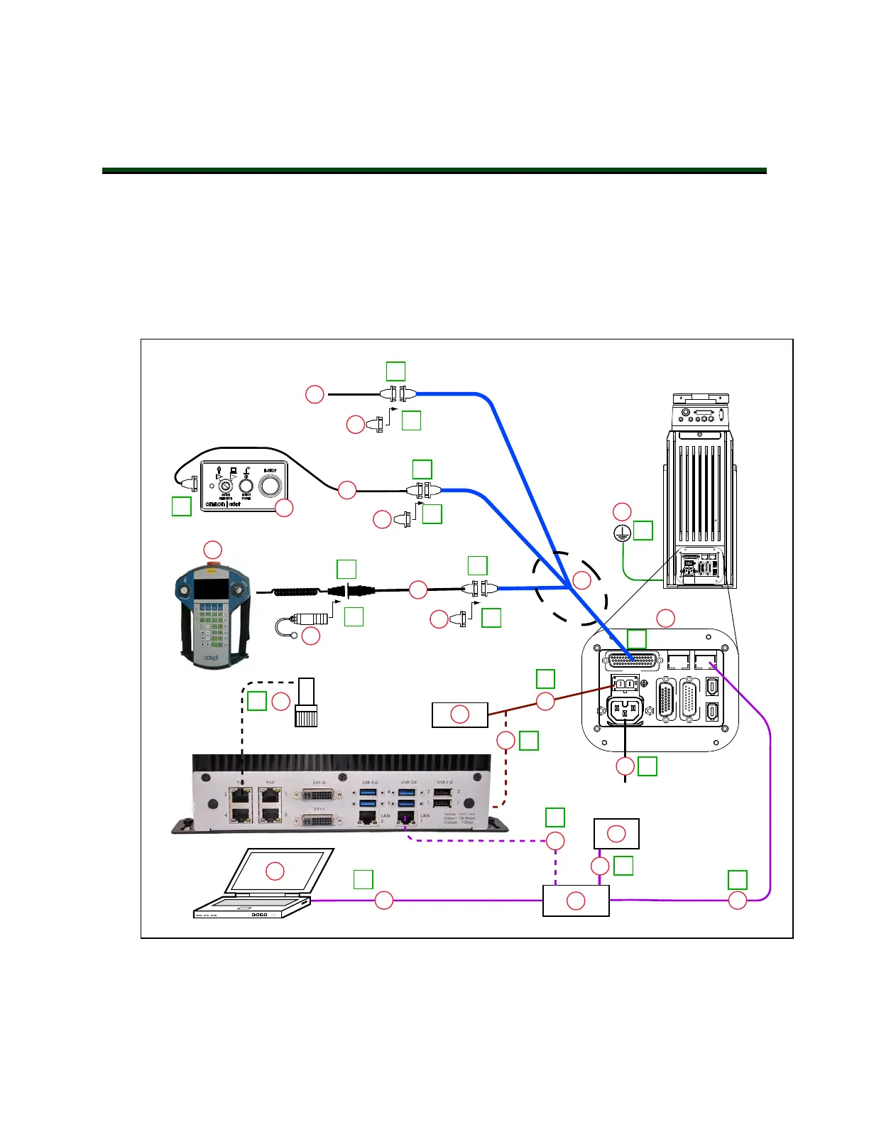
4.1 System Cables, without SmartController EX
The letters in the following figure correspond to the letters in Table 4-1. Cables and Parts
Description (without SmartController EX). The numbers in the following figure correspond to
the numbers in Table 4-2. Connections Installation Steps.
DC
IN
24 V
GND
AC
200 -
240 V
Ø
1
XBELTIO
XIO
Servo
ENETENET
XSYSTEM
XMCP
XFP
XUSR
B
P
O
N
L
J
I
H
G
F
E
D
C
T
S
R
A
U
200 - 240 VAC
2
2a
3
3a
4
4
4b
4a
5
7
8
8a
9
10
1
3
K
M
K
6
11
12
eCobra Robot
Q
V
W
SmartVision MX
DC
IN
24V
GND
AC
200 -
240V
Ø
1
XBELTIO
XIO
Servo
ENETENET
XSYSTEM
Figure 4-1. System Cable Diagram for eCobra Robots, Pendant and Vision Shown
14402-000 Rev. F eCobra User's Guide 35