Chapter 5: System Operation
5.5 Connecting Digital I/O to the System
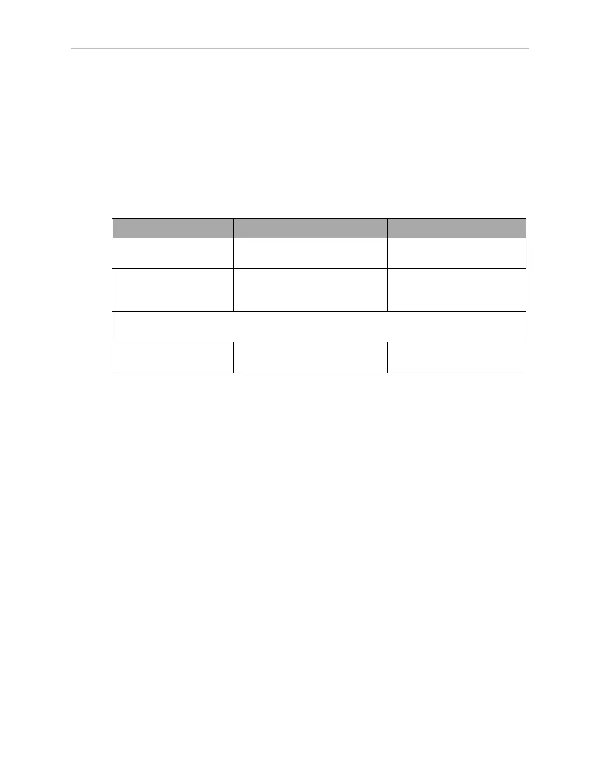
You can connect digital I/O to the system in several different ways. See the following table and
figure.
NOTE: A typical IOBlox configuration is shown in Figure 5-4. Other con-
figurations may be possible. Contact your local Omron support for more inform-
ation.
Table 5-3. Digital I/O Connection Options
Product I/O Capacity For more details
XIO Connector on robot 12 inputs
8 outputs
see eAIB XIO Connector Sig-
nals on page 86
Optional IO Blox Device,
connects to robot
8 inputs, 8 outputs per device;
up to eight IO Blox devices per
robot
see IO Blox User’s Guide. Not
available with eCobra Lite.
The following I/Oconnector and module require the optional SmartController EX motion con-
troller
XDIO Connector on
SmartController EX
12 inputs
8 outputs
SmartController EX User's
Guide
Optional I/O Products
These optional products are also available for use with digital I/O:
l
XIO Breakout Cable For information, see XIO Breakout Cable on page 93. This cable is
not compatible with the XIO Termination Block.
l
XIO Termination Block, with terminals for user wiring, plus input and output status
LEDs. Connects to the XIO connector with 6 foot cable. See the XIO Termination Block
Installation Guide for details.
14402-000 Rev. F eCobra User's Guide 83