30 eCobra User's Guide 14402-000 Rev. F
3.7 Mounting an eCobra 800 Inverted Robot
3.7 Mounting an eCobra 800 Inverted Robot
Mounting Surface
The eCobra 800 Inverted robot is designed to be mounted in an inverted position. When design-
ing the mounting structure, you must account for both load and stiffness. The mounting struc-
ture must be rigid enough to prevent vibration and flexing during robot operation. Excessive
vibration or mounting flexure will degrade robot performance. The mounting structure should
be stiff enough so that the first vibration mode is greater than 70 Hz.
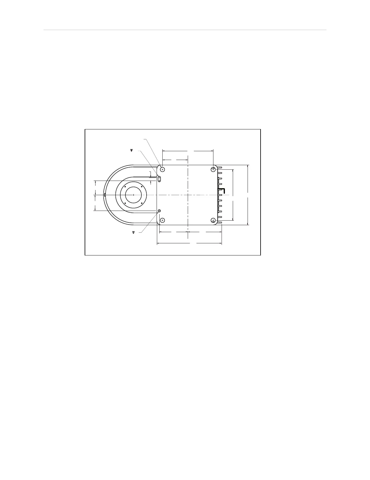
The following figure shows the mounting hole pattern.
45
50
10
80
107
90
160
205
160
189
4X Ø 14 Thru
Ø 8
2X R 4
+ 0.015
0.000
+ 0.015
0.000
6
6
Figure 3-3. Robot Mounting Dimensions for eCobra Inverted Robot (Units in mm)
NOTE: On the robot mounting surface, there is a hole and a slot that can be
used as locating points for user-installed dowel pins in the mounting surface.
Using locating pins can improve the ability to remove and reinstall the robot in
the same position.
Mounting Procedure
l
Always use at least two people, and preferably three, to mount the robot.
l
The robot should be in the folded position when lifting. See the following figure.