Chapter 3: Robot Installation
Figure 3-4. Robot in Folded Position (Units in mm)
WARNING: PERSONALINJURYORPROPERTYDAMAGERISK
Do not attempt to extend the inner or outer links of the robot until the robot has
been secured in position. Failure to comply could result in the robot falling and
causing either personnel injury or equipment damage.
1.
Using the dimensions shown in Figure 3-3. , drill and tap the mounting surface for four
M12 - 1.75 x 36 mm (or 7/16 - 14 UNC x 1.50 in.) machine bolts (mounting hardware is
user-supplied).
2.
If you are using dowel pins for locating the robot, insert those in the mounting surface.
3.
Remove the four screws on top of the wooden robot base protection box. See Figure 3-5.
l
Remove the robot base protection box.
l
Retain the four screws and box for possible later relocation of the equipment.
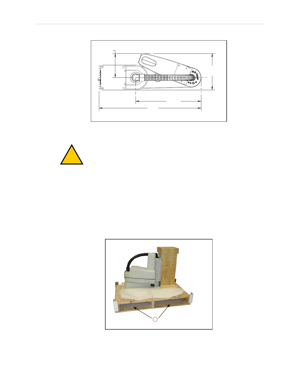
Figure 3-5. Pallet Lifting Device (1) Insertion Point
14402-000 Rev. F eCobra User's Guide 31