Chapter 8: Technical Specifications
Performance
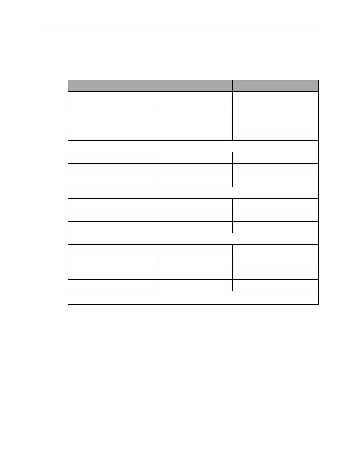
Table 8-11. eCobra Robot Performance
a
Description eCobra 600 Robot eCobra 800 Robots (both)
Moment of Inertia Joint 4 - 450 kg-cm²
(150 lb-in²) - max
Joint 4 - 450 kg-cm²
(150 lb-in²) - max
Downward Push Force—Burst,
(no load)
343 N (77 lb) - maximum 298 N (67 lb) - maximum
Lateral/Side Push Force—Burst 178 N (40 lb) - maximum 133 N (30 lb) - maximum
Adept Cycle—2 kg payload, sustained (no J4 rotation)
eCobra Lite 0.66 sec 0.73 sec
eCobra Standard 0.55 sec 0.62 sec
eCobra Pro 0.45 sec 0.54 sec
Repeatability
X, Y ±0.017 mm ±0.017 mm
Z ±0.003 mm ±0.003 mm
Theta ±0.019° ±0.019°
Joint Range
Joint 1 ±105° ±105°/±123.5° Inverted
Joint 2 ±150° ±157.5°/±156.5° Inverted
Joint 3 210 mm 210 mm
Joint 4 ±360° ±360°
a
Specifications subject to change without notice.
Stopping Distances and Times
The following graphs present information required by Clause 7.2 n) of ISO 10218-1. This
information should be used to calculate the safe distance needed when designing and
installing safeguarding devices.
The graphs show the time elapsed and distances traveled between the initiation of a stop sig-
nal and the cessation of all robot motion.
For stop category 1, the stopping time and distance values depend on the speed, load, and
extension of the robot, stated for 33%, 66% and 100% of the maximum payload (5.5kg). Data
provided is for the three joints of greatest displacement (J1, J2 and J3).
NOTE: Where lines overlap (and may not be visible) differences are not sig-
nificant.
14402-000 Rev. F eCobra User's Guide 167