28 eCobra User's Guide 14402-000 Rev. F
3.6 Mounting an Upright eCobra Robot
Table 3-3. Lifting Points for Robot while on a Transportation Pallet
Item Description
1 Eyebolt for lifting robot after robot has been unbolted from the transportation pallet.
2 Place for forklift or pallet-jack here.
WARNING: PERSONALINJURYORPROPERTYDAMAGERISK
Only qualified service personnel may install or service the robot system.
Mounting Surface
The upright eCobra robots are designed to be mounted on a smooth, flat, level surface. The
mounting structure must be rigid enough to prevent vibration and flexing during robot oper-
ation. We recommend a 25 mm (1 in.) thick steel plate mounted to a rigid tube frame. Excess-
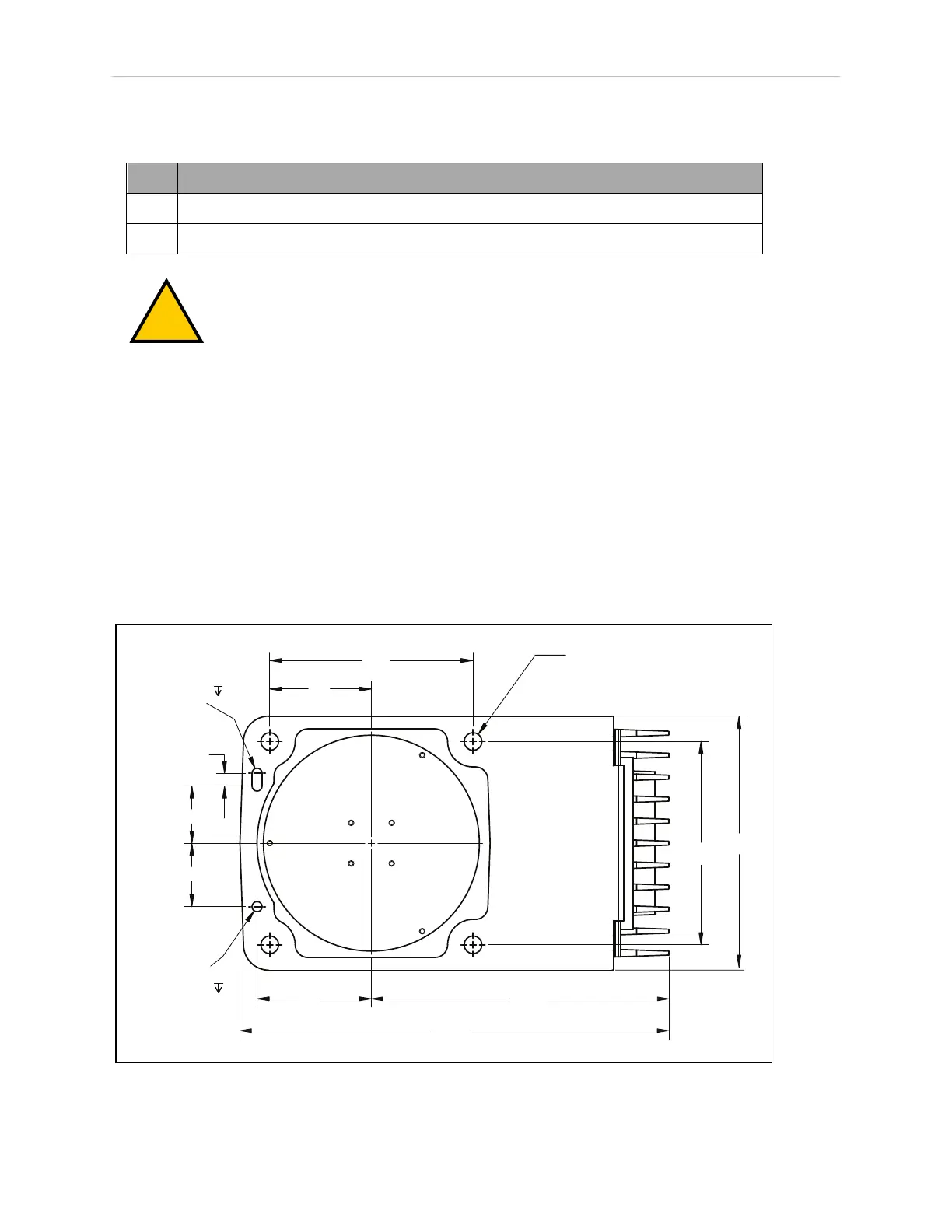
ive vibration or mounting flexure will degrade robot performance. The following figure shows
the mounting hole pattern for the eCobra robots.
NOTE: On the under side of the base there is a hole and a slot that can be used
as locating points for user-installed dowel pins in the mounting surface; see the
following figure. Using locating pins will improve the ability to remove and rein-
stall the robot in the same position.
+0.015
6
2x R4
0
45
50
10
160
160
200
80
90
+0.015
0
Ø 8
4X
Ø 14 THRU
6
234
338
Figure 3-2. Mounting Hole Pattern for Upright eCobra Robots (Units in mm)