Chapter 7: Optional Equipment Installation
Table 7-6. OP3/4 and SOLNDCircuit Descriptions
item Description Details
1 SOLNDConnector Circuit For optional Robot Solenoid Kit installation or
other user-supplied devices.
2 OP3/4 Connector Circuit For optional second set of solenoids or other user-
supplied devices.
3 +24 VDC (equivalent circuit)
EOAPWR Connector
This 4-pin connector provides 24 VDC power and ground for user applications. See the fol-
lowing table for the pinouts and the following section for the output specifications. For the con-
nector location, see Figure 7-4.
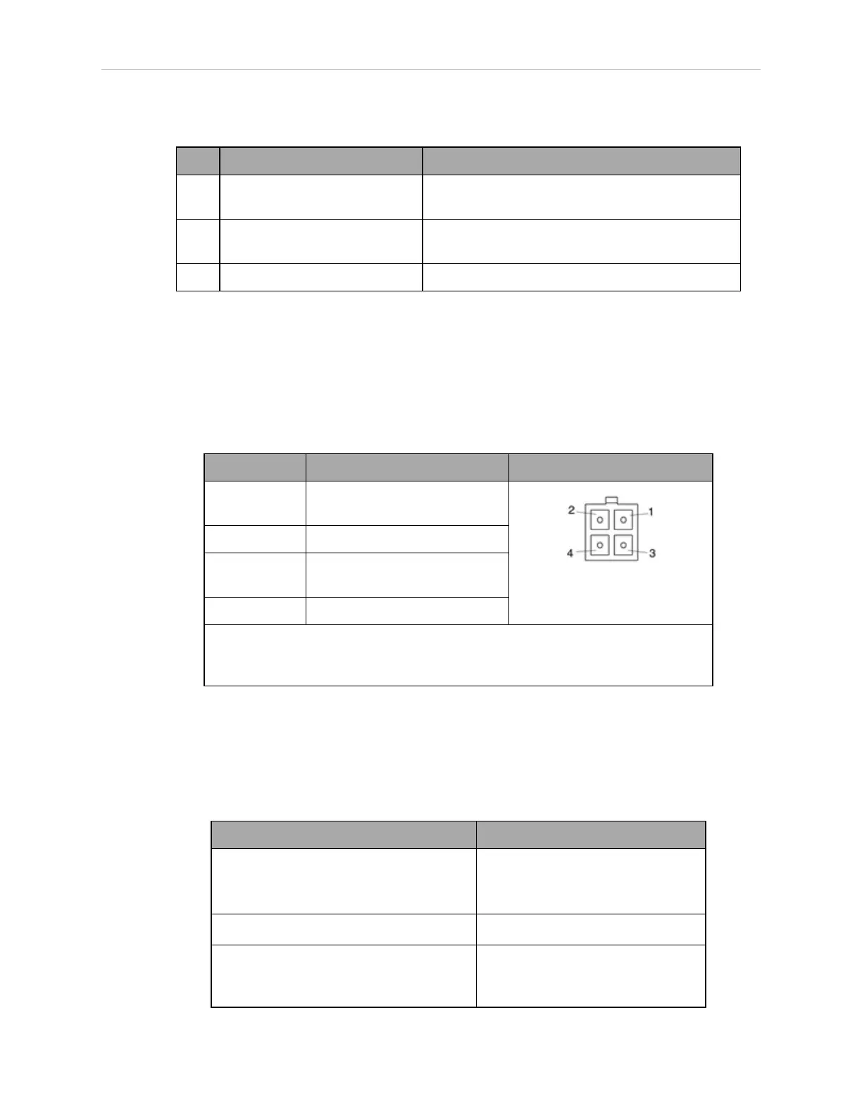
Table 7-7. EOAPWR Connector Pinout
Pin # Description Pin Location
1 24 VDC (see the next table for
current specs)
EOAPWR Connector
as viewed on robot
2 Ground
3 24 VDC (see the next table for
current specs)
4 Ground
Mating Connector:
AMP/Tyco #172167-1, 4-pin Mini-Universal Mate-N-Lok
AMP/Tyco #770985-1, Pin Contact, Mini-Univ. Mate-N-Lok
Internal User Connector Output Specifications
The output specifications in the following table apply to the EOAPWR, OP3/4, and SOLND
internal user connectors.
Table 7-8. Internal User Connector Output Circuit Specifications
Parameter Value
Power supply voltage range
24 VDC ± 10%
See Specifications for 24 VDC
Power on page 50.
Operational current range, per channel I
out
≤ 700 mA
Total Current Limitation, all channels
on
a
I
total
≤ 1.0 A @ 50° C ambient
I
total
≤ 1.5 A @ 25° C ambient
14402-000 Rev. F eCobra User's Guide 129