40 eCobra User's Guide 14402-000 Rev. F
4.2 System Cables, with SmartController EX
4.2 System Cables, with SmartController EX
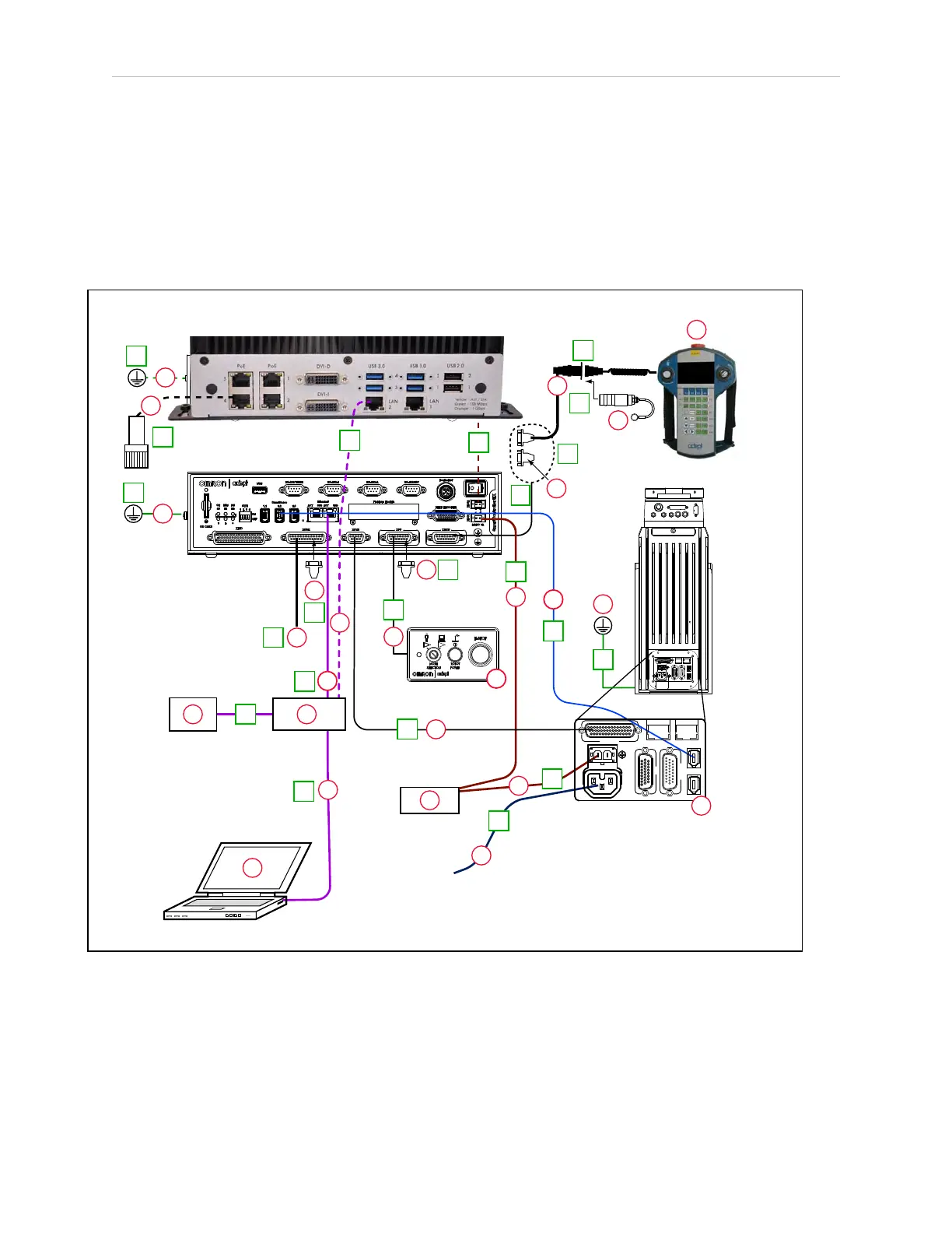
The letters in the following figure correspond to the letters in Table 4-3. Cables and Parts
Description (with SmartController EX). The numbers in the following figure correspond to the
numbers in Table 4-4. Connections Installation Steps(with SmartController EX).
When the optional SmartController EX is included in the system, the Pendant, Front Panel,
and XUSR connections must connect to the SmartController EX.
SmartController EX
COM1
COM2
MOUSE
KEYBD
DVI
VGA
LAN1
USB
LAN2
USB
LOUT
LIN
MIC
POWER
HDD SYS
24VCD 6A
_
+
SmartVision EX
SmartVision MX
eCobra Robot
200-240 VAC
10 A
DC
IN
24V
GND
AC
200 -
240V
Ø
1
XBELTIO
XIO
Servo
ENETENET
XSYSTEM
U
V
DC
IN
24 V
GND
AC
200 -
240 V
Ø
1
XBELTIO
XIO
Servo
ENETENET
XSYSTEM
D
A
E
1
8
3
3a
F
C
2
2a
B
4b
4
4a
4
G
H
K
5
8b
5
5
O
I
J
K
L
M
N
P
Q
R
S
T
6
8a
7
9
10
11
12
R
R
13
W
Figure 4-2. System Cable Diagram with SmartController EX