Section 2 NS Series Functions 2-21 System Settings and System Menu
2-499
NS Series Programming Manual
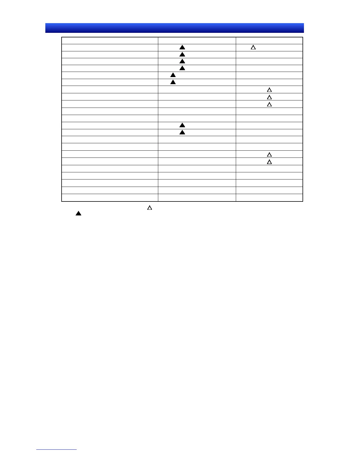
Item CX-Designer system setting PT System Menu
Host name (See note 9.) (See note 10.)
Host type (See note 9.) (See note 10.)
Network address (See note 9.) (See note 10.)
Node address (See note 9.) (See note 10.)
IP address (See notes 9 and 12.) (See note 12.)
Route path (See notes 9 and 12.) (See note 12.)
Operation log display
×
Alarm history display
×
Error log display
×
Device monitor
×
Communications test
×
Video Configuration (See note 5.)
Display Capture Data (See note 8.)
USB device list
×
(See note 13.)
PLC Data Trace
×
Version display
×
LCD check
×
Touch switch check
×
Touch panel Calibration (NS15 Only)
×
Video input method
×
Save in a file
×
Key Status Address
×
: Can be set, ×: Cannot be set, : Display only
: Can be set using different CX-Designer menu
Note 1. Set using Title Tab Page in the Project Property Dialog Box under PT - Project Properties.
2. Set using Switch Labels Tab Page in the Project Properties Dialog Box under PT - Project Properties.
3. Set in the Alarm/Event Parameter Setting Dialog Box, which is displayed when the Parameter Setting
Button is pressed. The Parameter Setting Button is found in the Alarm/Event Setting Dialog Box under
PT - Alarm/Event.
4. Set in the Password Setting Dialog Box under PT - Password setting.
5. Set in Video Control – Vision Sensor Console or Video Control – Contrast Adjustment in the Command
Button Setting Dialog Box to control images.
6. Set on the Select Language Tab of the Project Property Dialog Box under PT - Project Properties.
7. Set using Switch Labels Tab Page in the Project Property Dialog Box under PT – Project Properties.
8. A button to switch to the Display Capture Data screen can be created with the Display System Menu
command button function.
9. Set by selecting PT – Communication Setting on the Comm. Setting Dialog Box.
10. Only for hosts connected via Ethernet or Controller Link.
11. If the screen saver startup time is specified indirectly, only the allocated address will be displayed.
12. Only when connected to the host through EtherNet/IP. The setting cannot be changed if the host type
is set to EtherNet/IP,
13. Only printers connected to the USB host connector will be displayed. (PictBridge-compatible printers
will not be displayed.)
Refer to the System Settings and Project Properties settings in the CX-Designer Online Help and Sec-
tion 6 System Menu Operations in the NS Series Setup Manual (Cat. No. V083) for detailed explana-
tions of CX-Designer system settings and the PT System Menu.

 Loading...


