Section 2 NS Series Functions 2-13 Display
2-296
NS Series Programming Manual
2-13-6 Consecutive Line Drawings
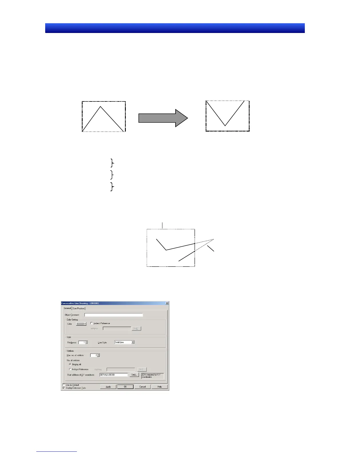
A consecutive line drawing is an object drawn within the object area using communications address
values as coordinates of the vertex points. Unlike regular polylines, these shapes can be changed dy-
namically. The top left vertex of the created object is the origin. If a vertex is outside of the object area,
that vertex will not be drawn.
Vertex 1 (0, 10)
Vertex 2 (10, 5)
Vertex 3 (20, 10)
The communications address values specify
each vertex’s X and Y coordinates.
(25,0) (0, 0)
(10,10)
The top-left point of the object is (0, 0).
$W100=0
$W101=10
$W102=10
$W103=5
$W104=20
$W105=10
The Start address of X-Y coordinate is set to $W100.
Coordinates of vertex 1
Coordinates of vertex 2
Coordinates of vertex 3
The vertices change as the
values of the communications
addresses change.
$W100=0
$W101=0
$W102=10
$W103=10
$W104=25
$W105=0
$W100=10
$W101=10
$W102=20
$W103=20
$W104=80
$W105=10
$W106=30
$W107=30
(20,20)
(10,10)
(30,30)
(80,10)
Created object area
Parts of the object
outside of the area are
not drawn.
The Start address of X-Y
coordinate is set to $W100.
Functional Object Property Settings
This section describes the functional object property settings in the Consecutive Line Drawing Window.
 Loading...


