Section 2 NS Series Functions 2-20 Special Functions
2-486
NS Series Programming Manual
2-20-12 PLC Data Trace
Like the CX-Programmer’s Data Trace function, the PT’s PLC Data Trace function uses the PLC’s built-in
Data Trace function and displays the results of the PLC’s Data Trace operation on the PT.
When the trigger condition is met after the PLC receives the command from the NS-series PT to execute
a data trace, the specified bit’s status or specified word’s present value is read according to the sampling
condition and that data is stored in the CPU Unit’s trace memory. The PT can read the data stored in the
PLC and display the data on-screen in a time chart.
The PLC Data Trace function is supported only in NS-series PTs with system version Ver. 6.6 or higher.
The function can be used in NS15, NS12, NS10, NS8, NSJ12, NSJ10, and NSJ8 PTs. The PLC Data
Trace function is compatible with CS1/CJ1/CJ2 Series and NSJ Series PLCs (excluding CP Series PLCs).
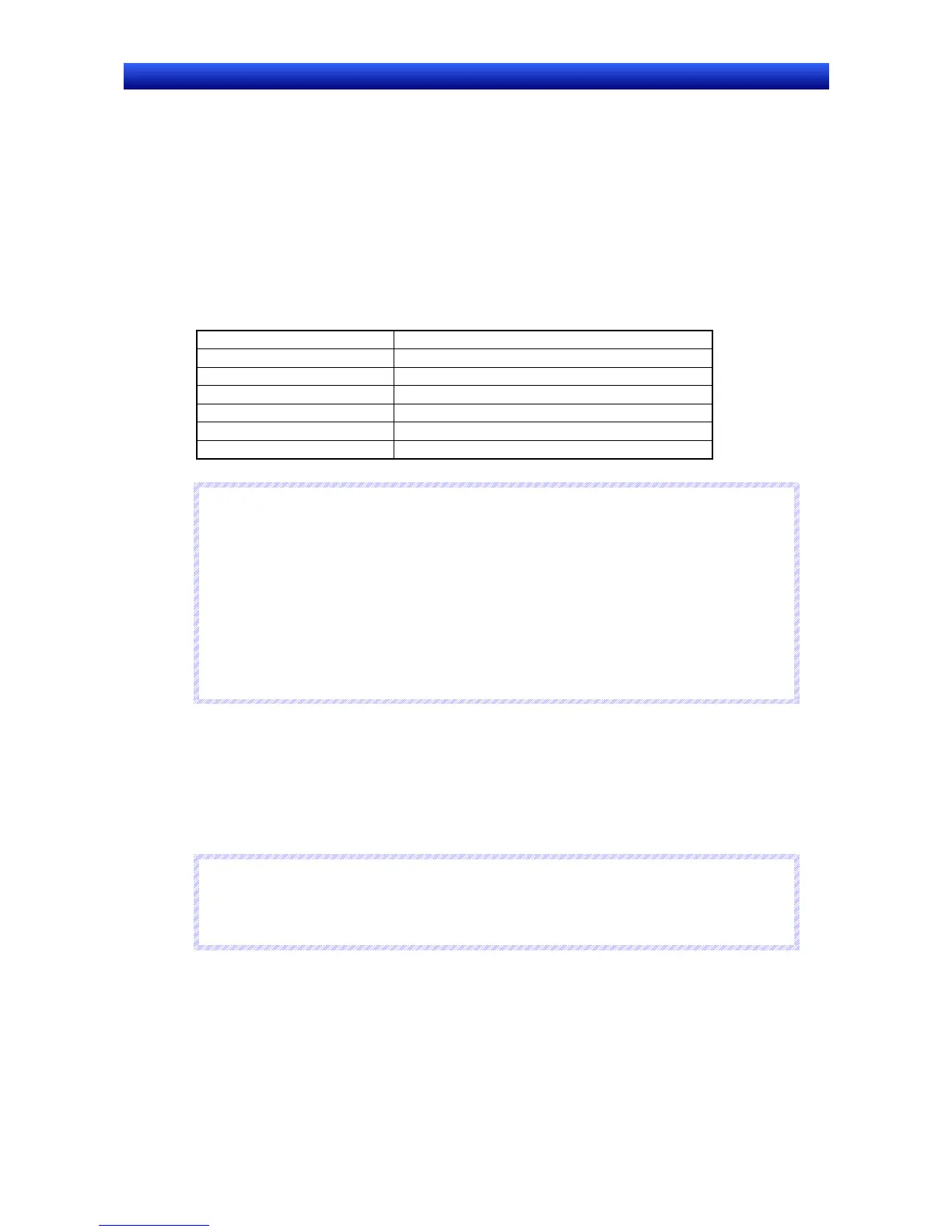
Specifications
Item Description
Sampling period During cyclic refreshing or once every 10 to 2,550 ms
Number of samples 2,000 samples
Number of bits in data trace 16 bits max.
Number of words in data trace 6 words max.
Trigger Only a bit condition can be set.
Trace start delay −1,999 to 2,000
R
R
R
e
e
e
f
f
f
e
e
e
r
r
r
e
e
e
n
n
n
c
c
c
e
e
e
♦
A word cannot be set for the trigger. The sampling method cannot be set to use execution of
TRSM instructions.
♦
The PLC Data Trace function is supported by the NS15, NS12, NS10, NS8, NSJ12, NSJ10, and
NSJ8 PTs.
The PLC Data Trace function is not supported by the NS5, NSJ5, or NSH-series PTs.
♦
Word PLC data trace cannot be performed with NS-series PT system versions that are lower than
version 8.0.
♦
The PLC Data Trace function is compatible with CS/CJ Series and NSJ Series PLCs.
For details on the Data Trace functions, refer to the PLC’s Operation Manual.
Starting and Exiting the PLC Data Trace Function
There are three ways to start the PLC Data Trace function.
1. Select Special Function – PLC Data Trace from the System Menu’s Special Screen Tab Page.
2. From the user screen, write 4501 BCD (1195 binary) to $SW0.
3. Execute a Multifunction Object for which displaying the system menu is set.
N
N
N
o
o
o
t
t
t
e
e
e
♦
The PLC Data Trace display will be switched between Japanese and English by the system
language setting. The system language can be switched with the Select Language setting in
the System Menu’s Initialize Tab Page.

 Loading...


