Section 2 NS Series Functions 2-4 System Memory
2-41
NS Series Programming Manual
R
R
R
e
e
e
f
f
f
e
e
e
r
r
r
e
e
e
n
n
n
c
c
c
e
e
e
♦
The password setting will not operate if the Function mode is set to enable passwords without
levels in the Password Setting Window. Refer to
2-8-15 Passwords (Expansion Tab) for details
on setting passwords.
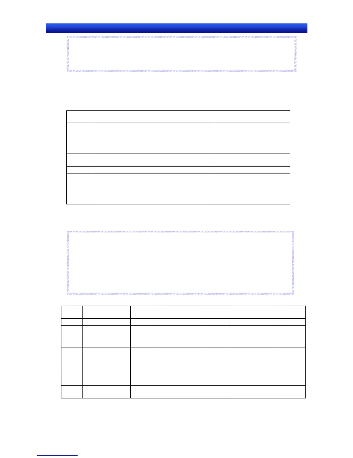
Range for Initializing Alarm/Event History ($SW40)
The option settings for initialization of alarm/event histories are made using $SB32.
The alarm/event history to be initialized using the value contained in $SW40 can be specified as
shown in the following table.
$SW40
value
Alarm/event history data initialized Remarks
0 All alarm/event history data Initializes all alarms/events, in-
cluding current and unconfirmed
alarms/events.
1 Cleared and confirmed alarm/event history data only Initializes alarms/events includ-
ing current alarms/events.
2 Cleared alarm/event history data only Initializes alarms/events includ-
ing unconfirmed alarms/events.
3 Confirmed alarm/event history data only
4 Resolved alarm/event history data and number of
occurrences
Initializes alarms/events includ-
ing unconfirmed alarms/events.
The current number of
alarm/event occurrences will be
set to 1.
Alarm/event history data is checked using the alarm/event summary/history object. Set the alarm his-
tory as the display data for the alarm/Event Summary/History object.
If $SW40 contains a value other than 0 to 4, $SB32 will not initialize when turned ON.
N
N
N
o
o
o
t
t
t
e
e
e
♦
All values stored in system word memory can be selected from either BCD or binary. Select BCD
or binary data storage for each group by pressing the System Memory List Button under Set-
tings - System Setting – Initial.
♦
BCD values starting with Fh will be handled as negative values. (The value range for system
word memory is –999 to 9999.)
♦
All addresses not specified above are reserved for system use. Do not access reserved ad-
dresses.
System word memory can be allocated to the following areas in the host PLC.
Symbol C-series PLCs Allocation
CVM1/CV-series
PLCs
Allocation CS/CJ-series PLCs Allocation
None I/O area (IR)
I/O area (CIO)
I/O area (CIO)
H HR Area
×
HR area
A AR Area
Auxiliary Area
×
Auxiliary Area
L Link Area
LR Area (See note 1.)
T Timer present values
×
Timer present val-
ues
×
Timer present values
×
TU
Timer Completion
Flags
×
C
Counter present val-
ues
×
Counter present
values
×
Counter present val-
ues
×
CU
Counter Completion
Flags
×

 Loading...


