Section 2 NS Series Functions 2-4 System Memory
2-43
NS Series Programming Manual
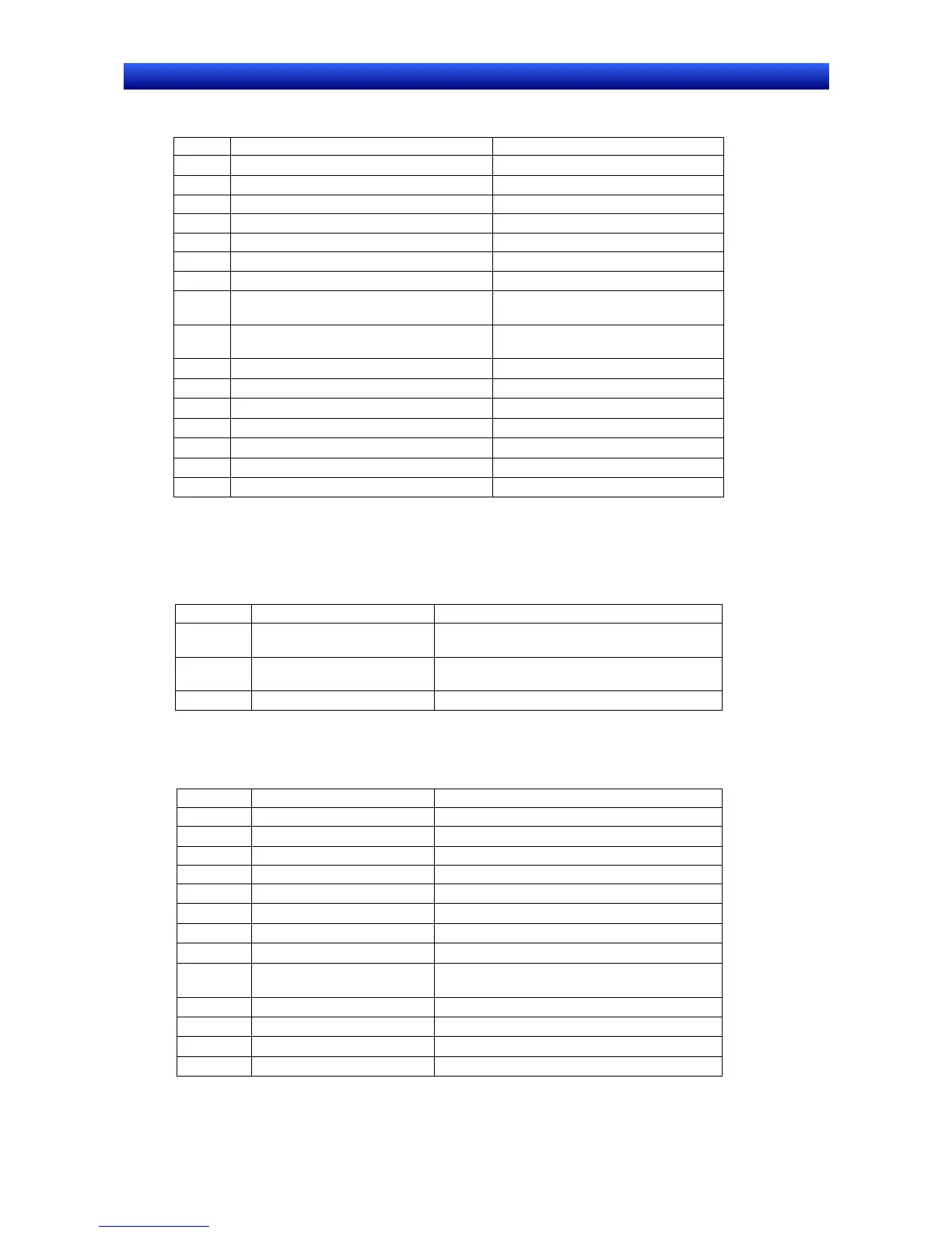
PT Status Control Bits
Bit Function Corresponding system memory
15 Not used
−
14 Not used
−
13 Continuous Buzzer (See note 2.) $SB12 (Continuous Buzzer)
12 Short Intermittent (See note 2.) $SB13 (Short Intermittent)
11 Initialize Alarm History (See note 2.) $SB32 (Initialize alarm/event history)
10 Not used
−
9 Long Intermittent (See note 2.) $SB14 (Long Intermittent)
8 Backlight Mode (ON: Lit, OFF: Flashing)
(See note 1.)
$SB10 (Backlight Flash Control)
7 Print Screen (See note 2.) $SB25 (Start Printing/Capture
Screen)
6 Not used
−
5 Not used
−
4 Not used
−
3 Not used
−
2 Not used
−
1 Not used
−
0 Not used
−
Note 1: The operation for Backlight Mode is different if NT compatibility is not used.
(The options if NT compatibility is not used are as follows: ON: Flashing, OFF: Lit.)
2: Notification will not be provided in the allocated PLC address even if the corresponding $SB is directly
manipulated. The value at the PLC address is always written to $SB.
The PT status notification area allocations are listed in the following table.
Word Function Corresponding system memory
m Screen Number (notification
only) (See note 1.)
$SW0 (currently displayed screen number)
m+1 Not used (always 0)
(See note 2.)
−
m+2 PT Status Notification Bits See the following table.
Note 1: Only numeric values in BCD format can be stored.
2: “0” is always written to the allocated address.
PT Status Notification Bit
Bit Function Corresponding system memory
15 PT Operation Status $SB1 (RUN Signal (always ON))
14 Not used
−
13 Battery $SB4 (Battery voltage low notification)
12 Screen Switch Strobe $SB2 (Screen Switch Strobe)
11 Not used
−
10 Not used
−
9 Not used
−
8 Not used
−
7 Printer Busy Status $SB30 (Printer Busy Status/Capture Busy
Status)
6 Not used
−
5 Not used
−
4 Not used
−
3 Not used
−

 Loading...


