3-20
Example
The
following example shows how to change parameter A1-02 to select Flux V
ector control (vector con
-
trol with pulse generator).
Key sequence Display Explanation
** Main Menu **
Operation
Displays operation mode.
** Main Menu **
Initialize
Displays initialize mode.
Select Language
English
Puts the Unit in initialize mode.
(Select Language display)
2 times
Control Method
Open Loop Vector
Displays the Control Method display.
A1-02= 2
Open Loop Vector
Displays the parameter setting for A1-02.
A1=02 3
Flux Vector
Changes the setting to Flux Vector.
Entry Accepted
Writes the new setting.
Control Method
Flux Vector
Returns to the Control Method display.
S Initializing the Parameters
Use
parameter A1-03 to initialize the parameters. This parameter cannot be
changed during operation.
Parameter Display name Setting Units Default
Valid access levels
number
range setting
V/f
Control
V/f
with PG
Open Loop
Vector
Flux
Vector
A1-03 Init Parameters 0, 1110,
2220, or
3330
--- 0 Quick-start, Basic, or Advanced
Initialize Parameters Settings
Setting Function
0 Returns to the Initialize display without initializing any parameters.
1110 Initializes the parameters to the user settings.
This
function initializes the parameters to values that have been recorded as user settings. T
o record
the
user settings, change the parameters to the desired
values and then set parameter o2-03 (User
Defaults) to 1. (The 1110 function is disabled when parameter o2-03 is 0.)
2220 2-wire sequential initialization (Initializes the parameters to the factory settings.)
3330 3-wire sequential initialization
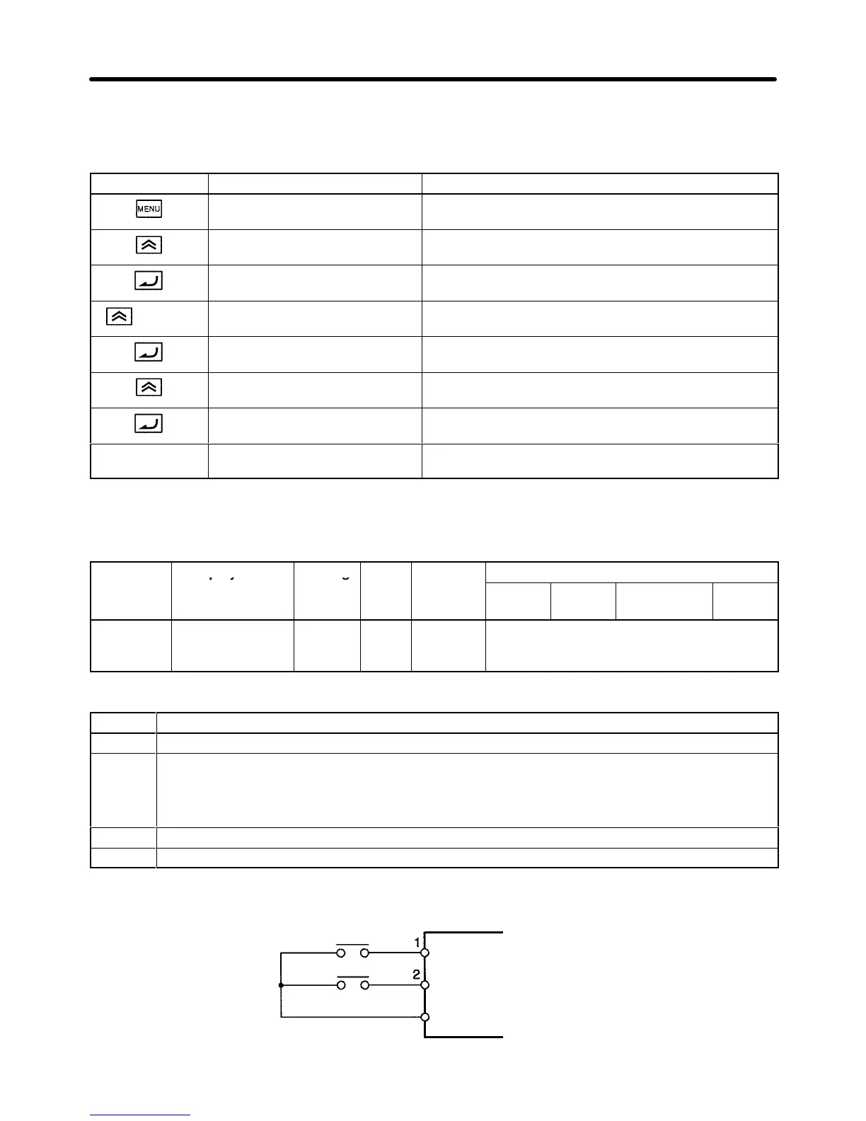
H Example of Wiring for 2-wire Sequential Operation
Forward rotation/Stop
11
Reverse rotation/Stop
Sequential input common
Preparing for Operation Chapter
3