4-9
Setting the V/f Pattern
• When
auto-tuning has not
been executed correctly (i.e., when “T
une Aborted” is displayed), switch the
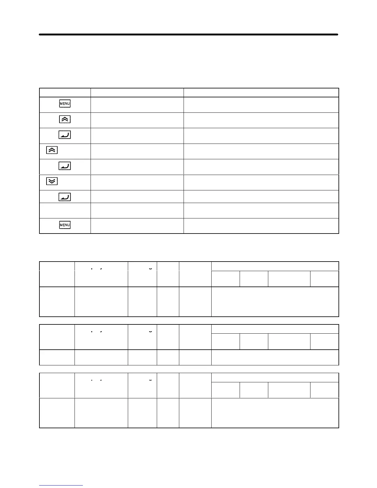
control mode to “V/f control” and set the V/f pattern.
• Procedure for changing the control mode.
Key sequence Display Explanation
** Main Menu **
Operation
Displays operation mode.
** Main Menu **
Initialize
Displays initialize mode.
Select Language
English
Puts the Unit in initialize mode. (Select Language
display)
2 times
Control Method
Open Loop Vector
Press the Up Arrow Key and the control mode select is
displayed.
A1-02= 2
Open Loop Vector
Control mode select (A1-02) is displayed.
2 times
A1-02= 0
V/f Control
Selects open-loop vector control.
Entry Accepted The set values are overwritten.
Control Method
V/f Control
Returns to the control mode select display.
** Main Menu **
Operation
Returns to the operation mode display.
• Set
the control mode to “V/f control,” and then set the following three items. These parameters cannot
be changed during operation.
Parameter Display name Setting Units Default
Valid access levels
number
range setting
V/f
Control
V/f with
PG
Open Loop
Vector
Flux
Vector
E1-05 Max Voltage 0.0 to
255.0
(0.0 to
510.0)
VAC 200.0
(400.0)
Quick-start, Basic, or Advanced
Parameter Display name Setting Units Default
Valid access levels
number
range setting
V/f
Control
V/f with
PG
Open Loop
Vector
Flux
Vector
E1-06 Base Frequency 0.0 to
400.0
Hz 60.0 Quick-start, Basic, or Advanced
Parameter Display name Setting Units Default
Valid access levels
number
range setting
V/f
Control
V/f with
PG
Open Loop
Vector
Flux
Vector
E2-01 Motor Rated FLA 10 to
200%
(See
note 1)
A See
note 2
Quick-start, Basic, or Advanced
Note 1. Inverter rated current ratio.
Note 2. The default setting for rated current differs according to the type of Inverter.
Trial Operation Chapter
4