5-52
The
multi-function analog outputs have the
following functions with these parameter settings. T
er-
minal
22 is the multi-function
analog output common. (There are separate commons, terminals 27
and 37, for the 3G3FV--CUE/CE.)
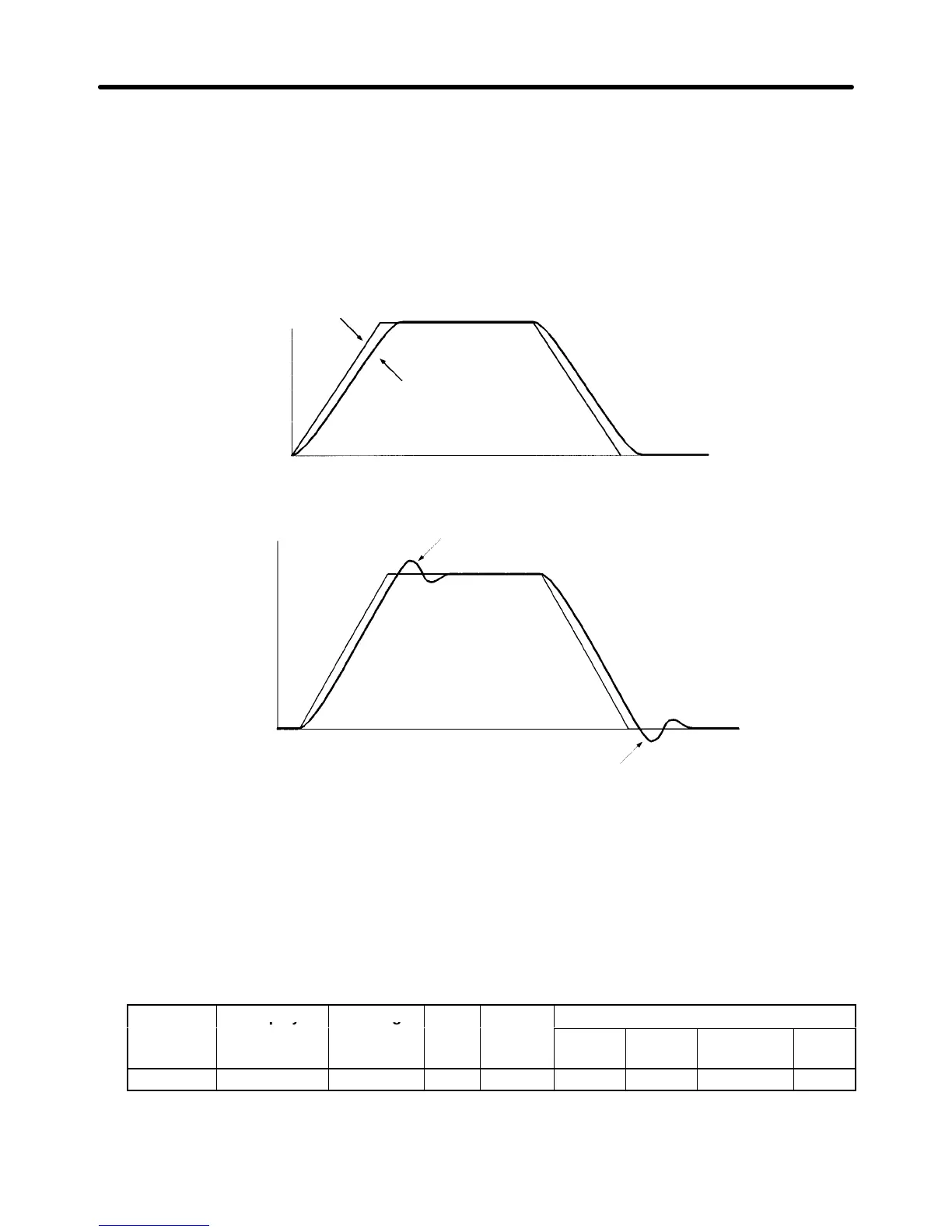
Multi-function analog output 1 (terminal 21): Outputs the Inverter’s ASR input (0 to ±10 V).
Multi-function analog output 2 (terminal 23): Outputs the actual motor speed (0 to ±10 V).
We
recommend
monitoring both the ASR input and the motor speed in order to observe a response
delay or deviation from the reference value, as shown in the following diagram.
Motor speed
ASR input command
Motor speed (response)
Time
3. Give acceleration/deceleration commands and adjust the gain while observing the waveform.
Motor
speed
If overshooting occurs:
Decrease C5-01 and increase C5-02.
If undershooting occurs:
Decrease C5-03 and increase C5-04.
4. If
the overshooting or undershooting can’t be eliminated by adjusting the gain,
decrease the ASR
limit (C5-05) to lower the frequency reference compensation limit. Since C5-05 can’t be changed
during
operation, stop the Inverter
’
s operation and then decrease the ASR
limit by 0.5 (%). Perform
step 3 again after the setting has been changed.
The
ASR limit is the frequency limit for compensation by speed control loop. Set
this frequency limit
as
a percentage of the maximum output frequency
. If the frequency limit is lowered too much, the
motor
speed might not
reach the target speed. V
erify that the target speed is reached during normal
operation.
Parameter Display Setting Units Default
Valid access levels*
number