6-10
Note The
setting range is 10% to 200% of the Inverter
’s rated output
current. The default setting de
-
pends
upon the type of Inverter
. (The table shows the default setting for 200-V class, 0.4-kW In
-
verters.)
Calculate
the rated slip (E2-02) from the value shown on the motor
’
s nameplate with the following equa
-
tion and set this value.
Rated slip = rated frequency (Hz) – rated speed (r/min) × number of poles/120
Set
the no-load current (E2-03) at the rated voltage and rated frequency
. Normally this value isn’t shown
on the motor’s nameplate, so it might be necessary to contact the motor manufacturer.
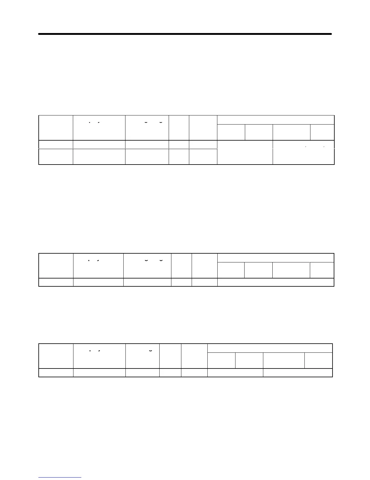
Parameter Display name Setting range Units Default
Valid access levels
number
setting*
V/f
Control
V/f with
PG
Open Loop
Vector
Flux
Vector
E2-02 Motor Rated Slip 0.00 to 20.00 Hz 2.90
Advanced Quick Start, Basic,
E2-03 No-Load Current 0.00 to 2.90
(see note 2)
A 1.20
or Advanced
Note 1. The
default setting depends upon the type of Inverter
.
(The table shows the default settings for
200-V class, 0.4-kW Inverters.)
Note 2. The setting range is between 0.00 and 0.1 less than the Inverter’s rated current.
Set the motor’s terminal resistance between U and V, V and W, or W and U.
Usually
the nameplate of the motor does not provide the motor
’
s terminal resistance. Contact the motor
manufacturer for a test report on the motor’s terminal resistance to set the following values.
• Type E insulation: Motor’s terminal resistance (Ω) at 75°C x 0.92
• Type B insulation: Motor’s terminal resistance (Ω) at 75°C x 0.92
• Type F insulation: Motor’s terminal resistance (Ω) at 115°C x 0.87
Parameter Display name Setting range Units Default
Valid access levels
number
setting
V/f
Control
V/f with
PG
Open Loop
Vector
Flux
Vector
E2-05 Term Resistance 0.000 to 65.000 Ω 9.842 Advanced
Note The default setting depends upon the type of Inverter.
(The table shows the default settings for 200-V class, 0.4-kW Inverters.)
Set
the voltage drop (caused by the motor
’
s leakage inductance) as a percentage of the motor
’
s rated
voltage in parameter E2-06. Normally this value is not shown on the motor
’
s nameplate, so it might be
necessary
to contact the motor manufacturer
. It is also acceptable to set the loss (caused by the motor
’s
leakage inductance) as a percentage.
Parameter Display name Setting Units Default
Valid access levels
number
range setting
V/f
Control
V/f with
PG
Open Loop
Vector
Flux
Vector
E2-06 Leak Inductance 0.0 to 40.0 % 18.2 Not applicable. Advanced
Note The default setting depends upon the type of Inverter.
(The table shows the default settings for 200-V class, 0.4-kW Inverters.)
The
default setting does not normally need to be changed because the Inverter in operation ad
-
justs
the leak inductance automatically
. Set the parameter if a high-speed motor or any other mo
-
tor with low inductance is used.
Parameters E2-07 and E2-08 are used in a frequency range even higher than the motor’s rated fre-
quency.
It isn’t necessary to set these parameters when operating below the motor
’
s rated frequency
.
Set the following values:
Advanced Operation Chapter
6