6-46
H Setting the Timer Function (b4)
The
timer function is enabled when the timer function input (set value: 18) and the
timer function output
(set
value: 12) are set for the multi-function input and
multi-function output respectively
. These inputs
and outputs serve as general-purpose I/O. Chattering of sensors, switches, and so on, can be pre-
vented by setting a delay time.
Parameter Display name Setting Units Default
Valid access levels
number
range setting
V/f
Control
V/f with
PG
Open Loop
Vector
Flux
Vector
b4-01
Delay-ON Timer
0.0 to
300.0
Sec 0.0 Advanced
b4-02 Delay-OFF Timer 0.0 to
300.0
Sec 0.0 Advanced
These parameters cannot be changed during operation.
• When
the timer function input ON time
is longer than the value set for b4-01 (timer function ON-delay
time), the timer function output turns ON.
• When the timer function input OFF time is longer than the value set for b4-02 (timer function OFF-
delay time), the timer function output turns OFF.
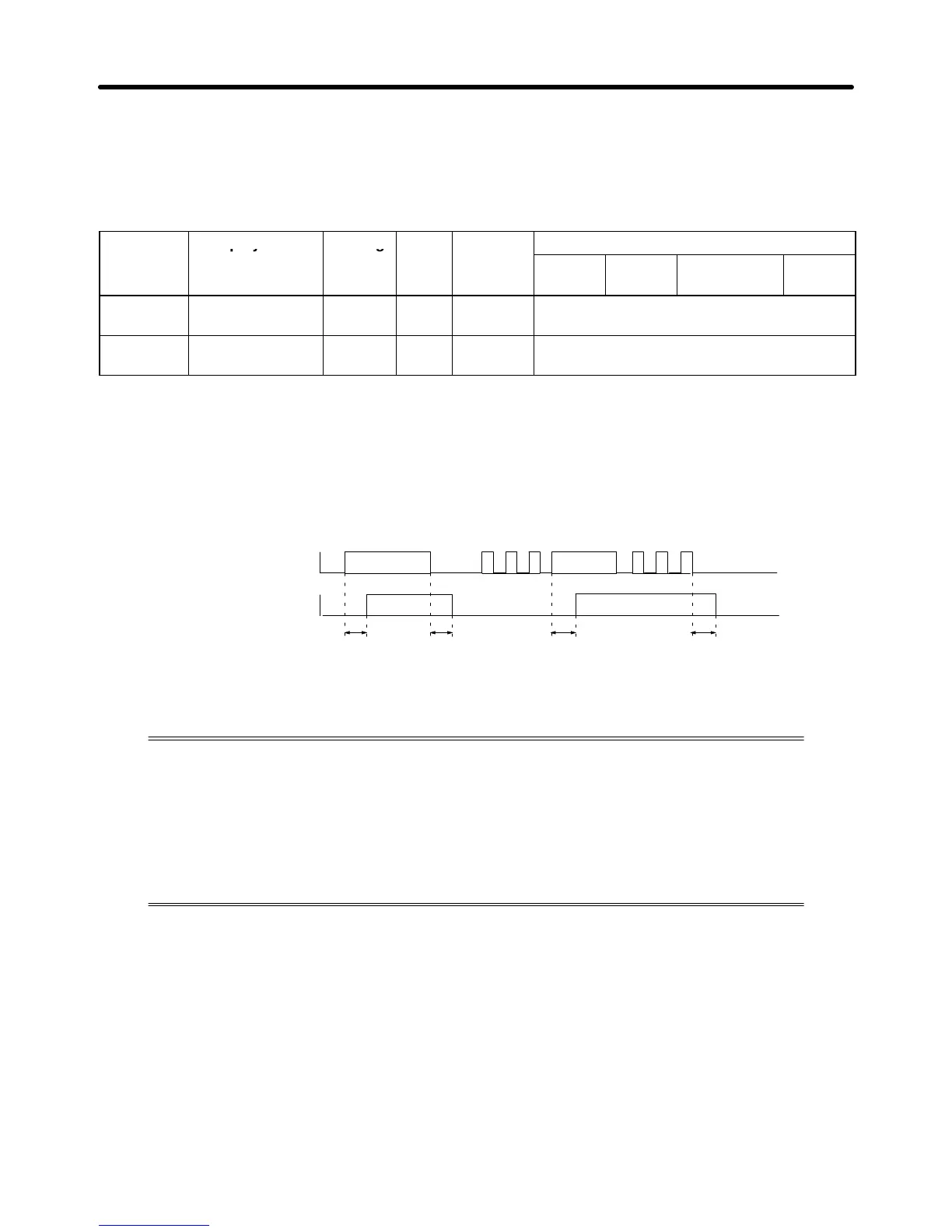
Operation Example
Timer function input
Timer function output
ON
ON ON
ON
b4-01 b4-02 b4-01 b4-02
H Setting PID Control (b5)
The
PID control function is a control system that matches a feedback value (i.e., a de
-
tected
value) to the set target value. Combining proportional (P), integral (I), and
deriva
-
tive (D) control makes control possible even for a mechanical system with dead time.
The
PID control provided by the SYSDRIVE 3G3FV
Inverter is not suited for control that
requires a responsiveness of 50 ms or less.
This
section explains the PID control applications and operations, along
with the param
-
eter settings and tuning procedure.
Advanced Operation Chapter
6