6-67
Note The above upper limit values are for 200-V class Inverters. Double the values for 400-V class
Inverters.
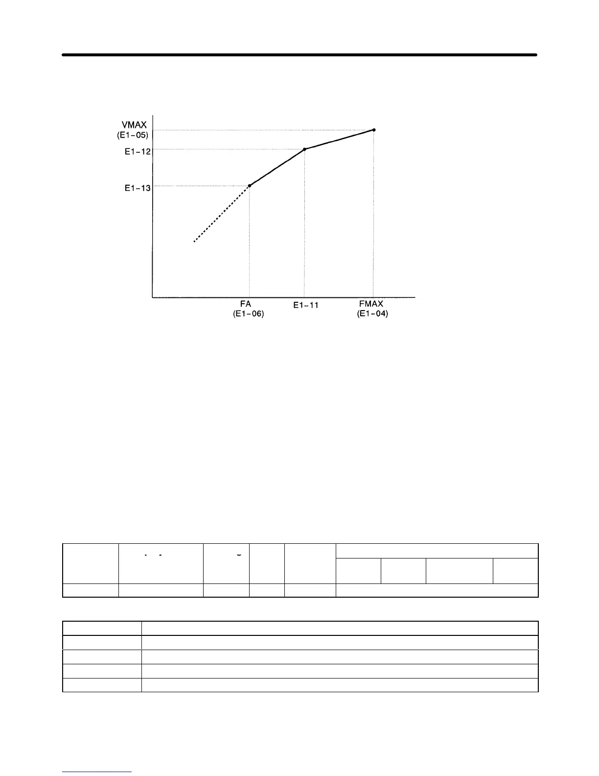
Output voltage (V)
Frequency (Hz)
Note 1. Set so that the following condition will be satisfied.
E1-06 x E1-11 x E1-04
Note 2. The function is disabled if the parameters E-11 and E1-12 are both set to 0.0.
Note 3. If auto-tuning is executed, the parameters E1-05 and E1-13 will be set to the set voltage.
H Two-motor Switching Control Function
This
function enables switching control between two motors using one Inverter
. The following function
additions were made to support this new functionality.
D Setting Control Mode and Motor Parameters for Second Motor
Set
the following parameter for the second motor
. The settings of parameters E1 and E2 are used for the
first motor.
If
the motor is operated in flux or open-loop vector control mode, set
the motor selection for auto-tuning
to 2.
Parameter Display name Setting Units Default
Valid access levels
number
range setting
V/f
Control
V/f with
PG
Open Loop
Vector
Flux
Vector
E3-01 Control Method 0 to 3 --- 2 Advanced
Explanation of Settings
Setting Description
0 Normal V/f control
1 V/f control with PG
2 Open-loop vector control
3 Flux vector control
Set the control mode for the second motor
. The set value will not be set to the default value when the
Inverter is initialized.
Advanced Operation Chapter
6