6-71
D Installation Procedure
1. Turn
of
f the Inverter
’
s main-circuit power supply
. W
ait at least one minute (or at least three minutes
for models of 30 kW or more), and then remove the Inverter
’
s front cover
. Check to be sure that the
CHARGE light is turned OFF.
2. Check the Optional Card’s installation location (A, C, or D).
Type of card Model Specifications Location
Analog Reference
3G3IV-PAI14U 14-bit analog, 2 inputs (voltage/current) C
Card
3G3IV-PAI14B 14-bits analog, 3 inputs C
Digital Reference
3G3IV-PDI08 8-bit digital input (BCD/binary) C
Card
3G3IV-PDI16H2 16-bit digital input (BCD/binary) C
PG Speed Control
3G3FV-PPGA2 Open-collector-compatible, single input A
Card
3G3FV-PPGB2 Open-collector-compatible, A/B-phase input A
3G3FV-PPGD2 Line-driver-compatible, single input A
3G3FV-PPGX2 Line-driver-compatible, A/B-phase input A
Analog Monitor Card
3G3IV-PAO08 8-bit analog output, 2 channels D
3G3IV-PAO12 12-bit analog output, 2 channels D
Pulse Monitor Card 3G3IV-PPO36F Pulse frequency output D
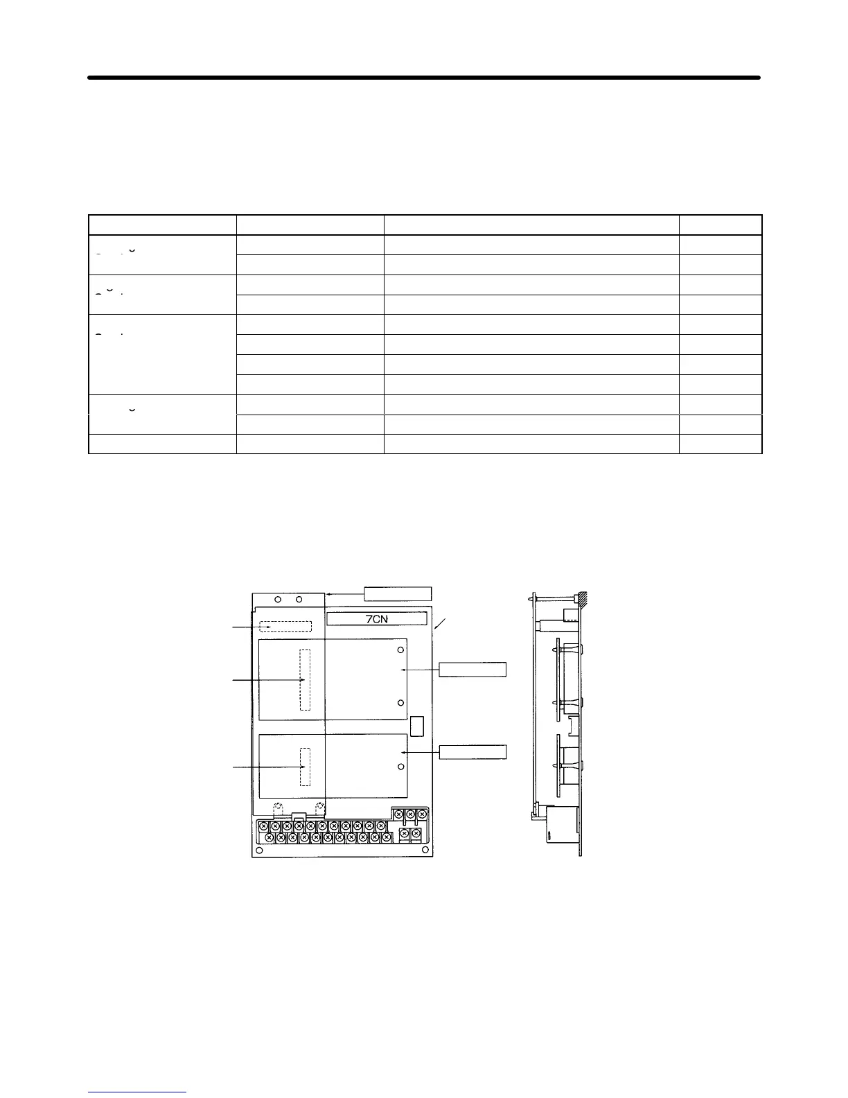
3. Insert the accessory spacer into the spacer mounting hole in the Inverter’s mounting base.
4. Align
the Optional Card connector with the connector position on the control board, and then pass
the
spacer
through the spacer mounting hole on the card. Press firmly until the spacer snaps into
place.
5. Connect the Optional Card’s FG connection line to the Inverter’s FG terminal (terminal 12).
4CN
Option A connector
2CN
Option C connector
3CN
Option D connector
Option A
Control board
Option C
Option D
Inverter’s mounting base
Front View
Side View
H Setting a Analog Reference Card (F2)
When
using a 3G3IV
-PAI14B/PA1
14U Analog
Reference Card, set parameter b1-01 (reference selec
-
tion) to “3” (option).
When
using a 3G3IV
-P
AI14B, set
the function for channels 1 to 3 with parameter F2-01. (There are no
parameters to set for 3G3IV-PAI14U.)
Advanced Operation Chapter
6