6-74
Explanation of Settings
Setting Description
0 1F
1 6F
2 10F
3 12F
4 36F
Note “F”
indicates
the output frequency (Hz). For example, if “0” (1F) is set, when the output frequency
is 60 Hz there will be an output of 60 pulses per minute. (Duty 50%)
H Setting a Wired SYSMAC BUS Interface Card (F8)
When
using a 3G3IV
-PSIG Wired SYSMAC BUS Interface Card, set the following parameter
in order to
specify the operation of the Inverter for communications failures.
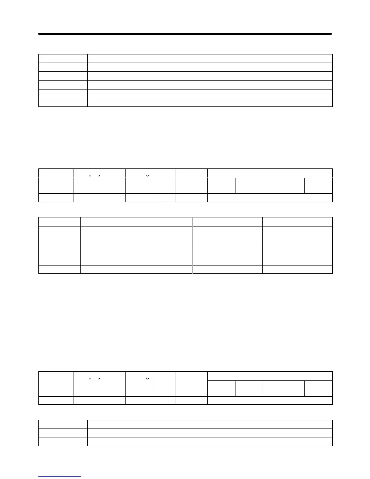
Parameter Display name Setting Units Default
Valid access levels
number
range setting
V/f
Control
V/f with
PG
Open Loop
Vector
Flux
Vector
F8-01 E-15 Det Sel 0 to 3 --- 1 Basic or Advanced
Set the parameter according to the application.
Setting Description Inverter’s status Fault output
0 Deceleration 2: Decelerates to a stop
with C1-02 set.
Fault ON
1 Coast to a stop. Fault ON
2 Emergency stop time: Decelerates to a
stop according to the C1-09 setting.
Fault ON
3 Continuous operation. (See note.) Alarm OFF
Note If
the parameter is set to 3, the Inverter will operate without references from the host controller
.
Take necessary measures, such as emergency stop measures, to ensure safety.
H Setting a CompoBus/D Communications Card (F9)
When using a 3G3FV-PDRT1-SIN CompoBus/D Communications Card, make the communications
settings with the following parameters.
D Setting Communications External Fault Input
Set the following three parameters to specify the detection method of communications external fault
input.
Parameter Display name Setting Units Default
Valid access levels
number
range setting
V/f
Control
V/f with
PG
Open Loop
Vector
Flux
Vector
F9-01 EF0 Selection 0, 1 --- 0 Basic or Advanced
Explanation of Settings
Setting Description
0 Normally open contact. (A communications external fault is input with the bit turns ON.)
1 Normally close contact. (A communications external fault is input with the bit turns OFF.)
Advanced Operation Chapter
6