6-81
• When
parameter d4-01 (the frequency reference hold function selector) is set to 1, the held frequency
will
be stored
in memory
. This stored frequency will be retained even after a power interruption and the
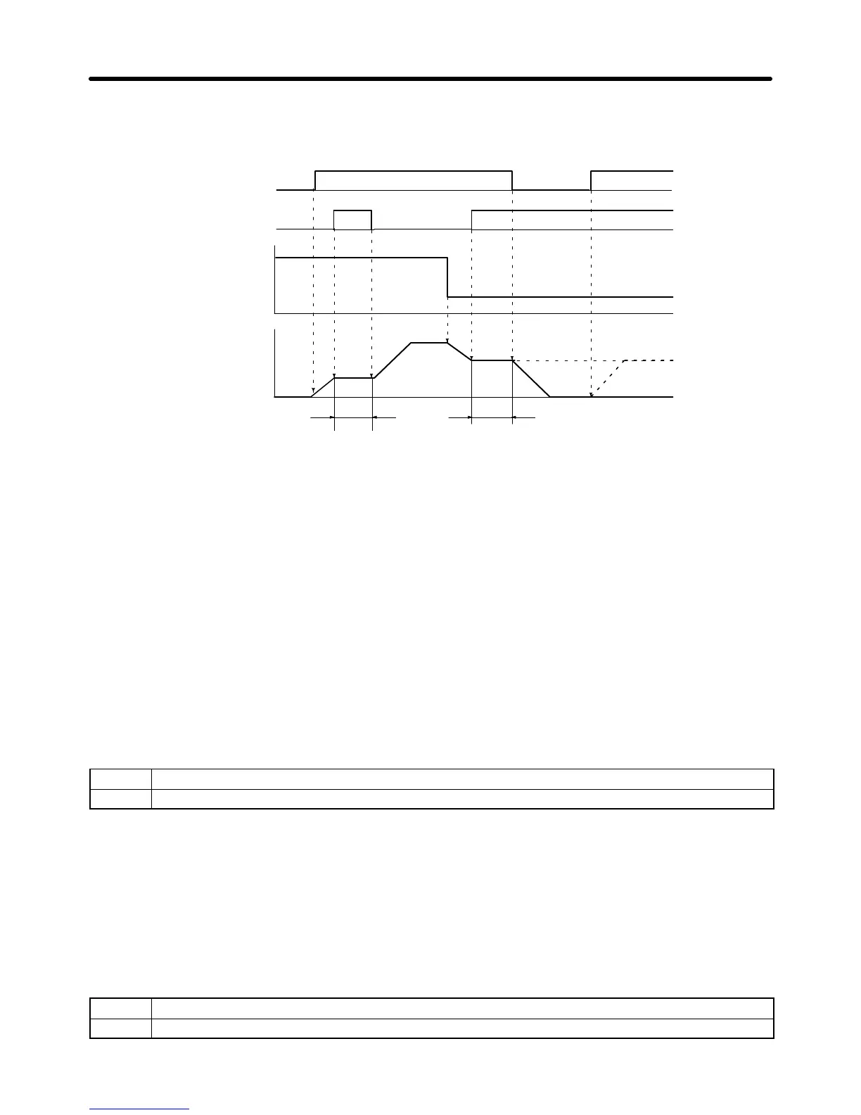
motor will be restarted at this frequency when a run command is input again.
Run/Stop command
Frequency reference
Output frequency
Hold
Acceleration/deceleration
ramp hold
Hold
ONOFF ON
ONOFF ONOFF
OFF
d4-01 = 1
d4-01 = 0
Note 1. When
d4-01 is
set to 1, the held output frequency will be retained. T
o operate at this frequency
even
after the Inverter is stopped, input the run command
with the acceleration/deceleration
ramp hold input ON.
Note 2. When
d4-01 is set to 0, the
output frequency will be held at zero if the run command is input
with the acceleration/deceleration ramp hold input ON.
Note 3. Select
and set one of the following functions for multi-function input. Do not set more than one
of them, otherwise a setting error (OPE3) will result.
S Acceleration/Deceleration Ramp Hold (Setting: A)
S UP and DOWN Commands (Settings: 10 and 11)
S Trim Control Increase and Decrease (Settings: 1C and 1D)
S Analog Frequency Reference Sample/Hold (Setting: 1E)
D OH2 Alarm Signal (Setting: B)
OFF Normal operation
ON Normal operation (The warning message “OH2” will be displayed on the Digital Operator.)
• With
this
setting, a temperature sensor can be connected to the multi-function input to display a warn
-
ing message when the temperature rises too high.
• The
message “OH2” will be displayed on the Digital Operator while the multi-function input is ON and
the
display will revert to its previous status when the input is turned OFF
. (It isn’t necessary to reset the
alarm.)
• The Inverter will continue operation without detecting a fault.
D Terminal 16 Enable (Setting: C)
OFF Disables the multi-function analog input (terminal 16).
ON Enables the multi-function analog input (terminal 16).
Advanced Operation Chapter
6