6-100
• Set the power-loss ridethrough time in seconds.
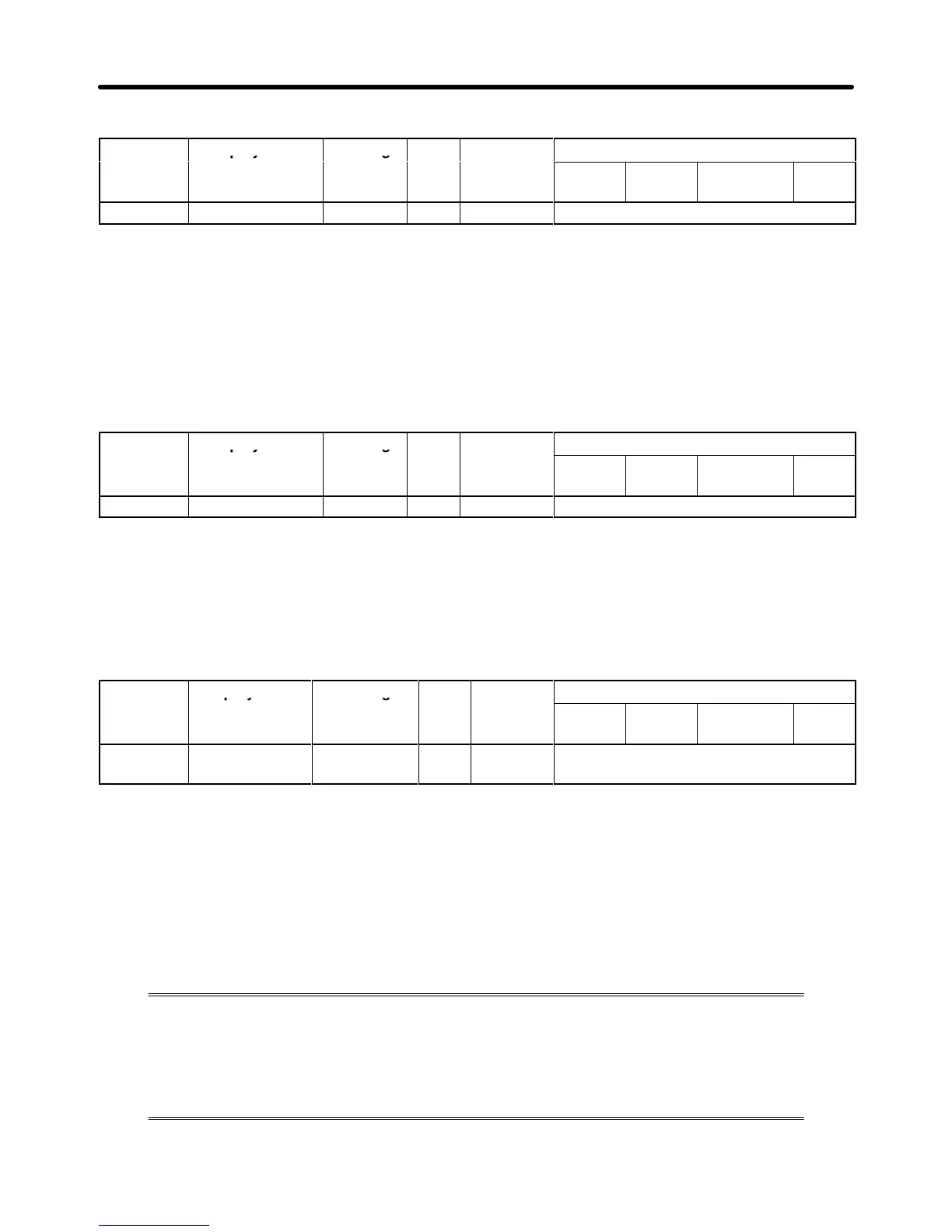
Parameter Display name Setting Units Default
Valid access levels
number
range setting
*2
V/f
Control
V/f with
PG
Open Loop
Vector
Flux
Vector
L2-03 PwrL Baseblock t 0.1 to 5.0 s 0.3 Basic or Advanced
Note 1. This parameter cannot be changed during operation.
Note 2. The
default
setting varies with the Inverter
’
s capacity
. The setting for 200-V class, 0.4-kW In
-
verters is shown.
• This setting is used with the speed search and DC braking functions.
• Set
the time required for the leakage voltage to dissipate. Increase the setting if
an overcurrent (OC)
occurs when the speed search or DC braking function starts.
• This
setting is valid for speed searches performed after a momentary power loss and regular speed
searches.
Parameter Display name Setting Units Default
Valid access levels
number
range setting
V/f
Control
V/f with
PG
Open Loop
Vector
Flux
Vector
L2-04 PwrL V/F Ramp t 0.1 to 5.0 s 0.3 Advanced
Note This parameter cannot be changed during operation.
• Set the time allowed for the normal voltage to be restored after completion of the speed search.
• For
a 200-V class Inverter
,
this is the time in seconds for voltage to be restored from 0 V
AC to 200 V
AC.
For a 400-V class Inverter
, this is the time in seconds for voltage to be restored from 0 V
AC to 400 V
AC.
• This setting is valid for speed searches after a momentary power loss, regular speed searches, the
voltage changes with energy-saving control, and the voltage changes with baseblock clearing.
Parameter Display name Setting Units Default
Valid access levels
number
range setting
V/f
Control
V/f with
PG
Open Loop
Vector
Flux
Vector
L2-05 PUV Det Level 150 to 210
(300 to 420)
V 190 (380) Advanced
Note 1. This parameter cannot be changed during operation.
Note 2. The values in parentheses are for 400-V class Inverters.
• Normally it isn’t necessary to change this setting.
• Use this parameter when you want to add an AC reactor and lower the main circuit under-voltage
detection
level. Be sure to set a main circuit DC voltage value (V) that will detect a main circuit under-
voltage.
H Stall Prevention Function Settings (L3)
A stall occurs if the rotor cannot keep up with the rotating magnetic field on the motor
stator
side
when a large load is applied to the motor or a sudden acceleration/decelera
-
tion is performed.
In
the 3G3FV
, stall prevention functions can be set independently for accelerating, run
-
ning,
and decelerating. (Some functions are restricted
depending on the control mode.)
Advanced Operation Chapter
6