8-10
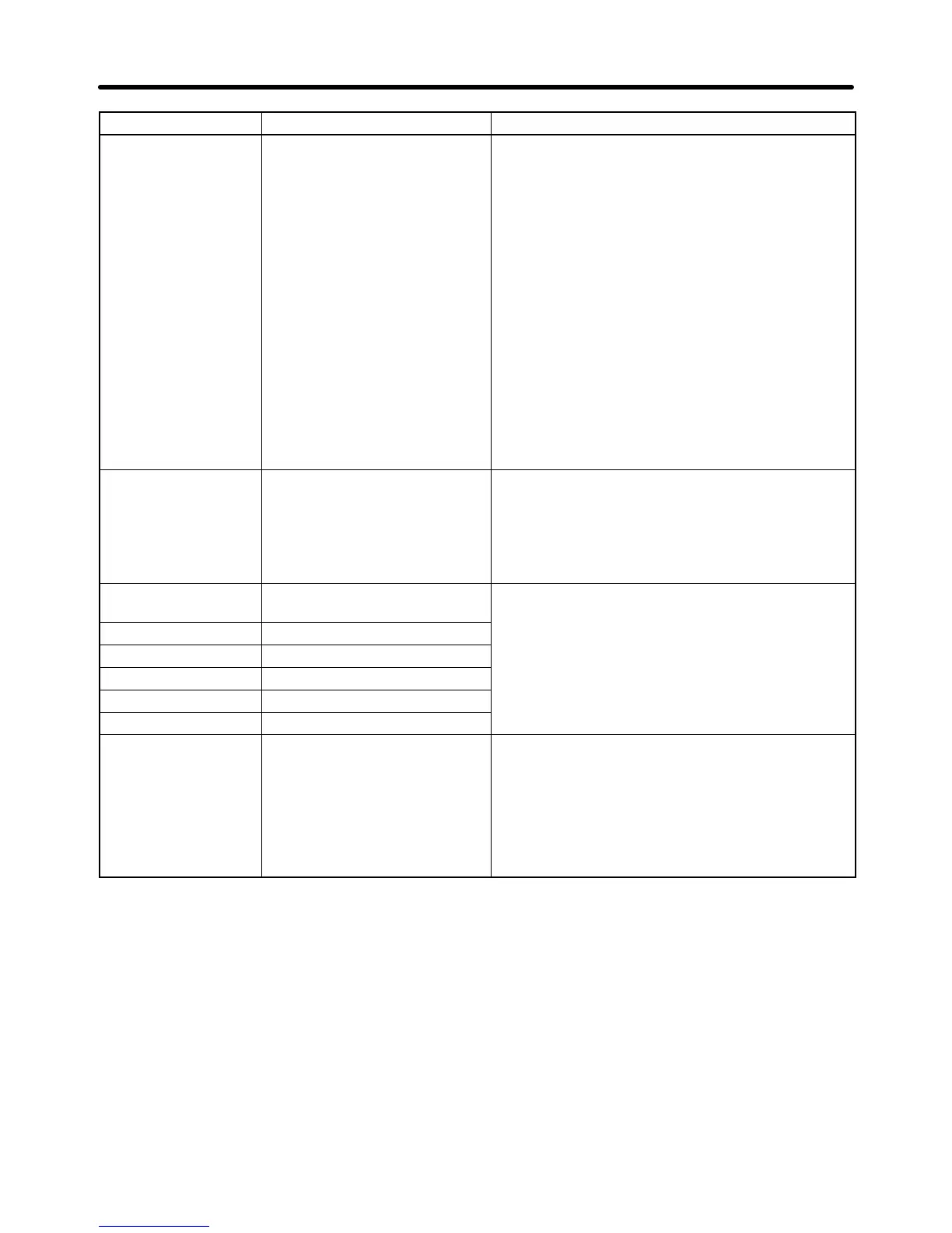
Minor fault display Probable causes and remediesMeaning
DEV (flashing)
Speed Deviation
The speed deviation has been
greater than the setting in
F1-10 for longer than the
setting in F1-11.
• The load is too large.
→ Lighten the load.
• The acceleration time and deceleration time are
too short.
→ Lengthen the acceleration time and decelera-
tion time.
• The load is locked.
→ Check the mechanical system.
• The
settings in F1-10 and
F1-1
1 aren’t appropriate.
→ Check the settings in F1-10 and F1-11.
• The torque limit is set to 0 through CompoBus/D
communications. (Applies only to flux vector con-
trol.)
→ Set F9-05 to 0 (torque limit disabled).
EFO
Opt External Flt
External fault
(Communications/option)
• An
external fault was
input from an Optional Com
-
munications Card.
→ Reset
the external fault from the Optional
Com
-
munications Card.
→ Remove the cause of the external fault input.
EF3 (flashing)
External Fault 3
External fault (Input terminal 3)
• An
external fault was input from a multi-function in
-
put.
EF4 (flashing) External fault (Input terminal 4)
.
EF8 (flashing) External fault (Input terminal 8)
CALL
SI-F/G ComCall
SYSMAC BUS CALL error
Only 00 was received since
communications were
established.
Only 00 was transmitted since communications
were established and the host was ready.
Note The Inverter waits for the host to be ready.
Clear this standby state by sending data.
→ Correct
the program so
that data other than 00
is sent first after communications are estab-
lished.
Maintenance Operations Chapter
8