8-13
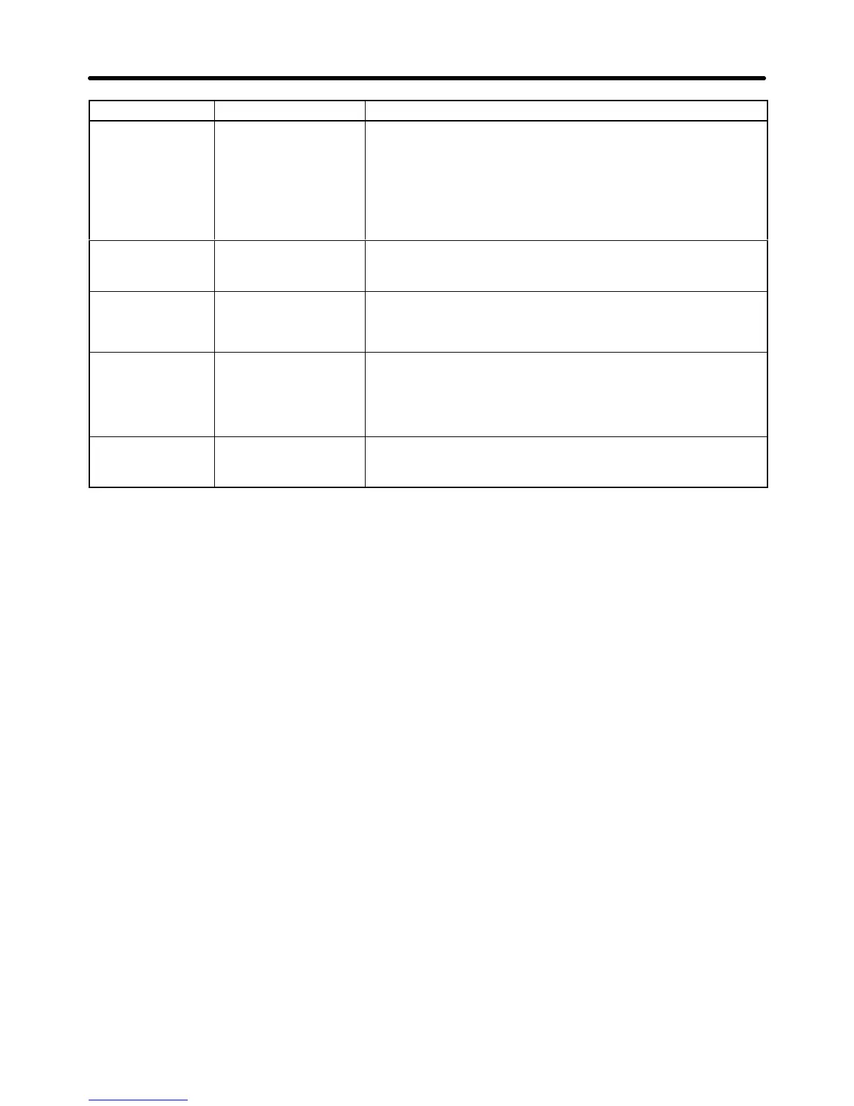
Display Incorrect settingsMeaning
OPE07
Analog Selection
Multi-function analog
input selection error
• The
same setting (other than 1F) has been selected for H3-05
and H3-09.
• A 3G3IV-PA114B Analog Reference Card is being used and
F2-01
is set to 0, but
a multi-function input (H1-01 to H1-06) has
been set to Option/Inverter Selection (2).
• Frequency
Bias and Frequency Bias 2 are set at the same time.
OPE08
Function Setting
Function setting error Functions that cannot be controlled by the current control
mode are set. (For example, the torque reference was set in
V/f control.)
OPE10
V/f Ptrn Setting
V/f data setting error • Parameters
E1-04, E1-06, E1-07, and E1-09 do not satisfy
the
following conditions:
• E1-04 (F
MAX
) ≥ E1-06 (F
A
) > E1-07 (F
B
) ≥ E1-09 (F
MIN
)
OPE11
CarrFrg /
On-Delay
Parameter setting
error
• One of the following parameter setting errors exists.
• The carrier frequency upper limit (C6-01) > 5 KHz and
the carrier frequency lower limit (C6-02) ≤ 5 KHz.
• The
carrier frequency gain (C6-03) > 6 and (C6-01) < (C6-02).
ERR (flashing)
EEPROM R/W Err
A verification error
occurred when writing
EEPROM.
→ Try turning the power supply off and on again.
→ Try setting the parameters again.
Maintenance Operations Chapter
8