2-16
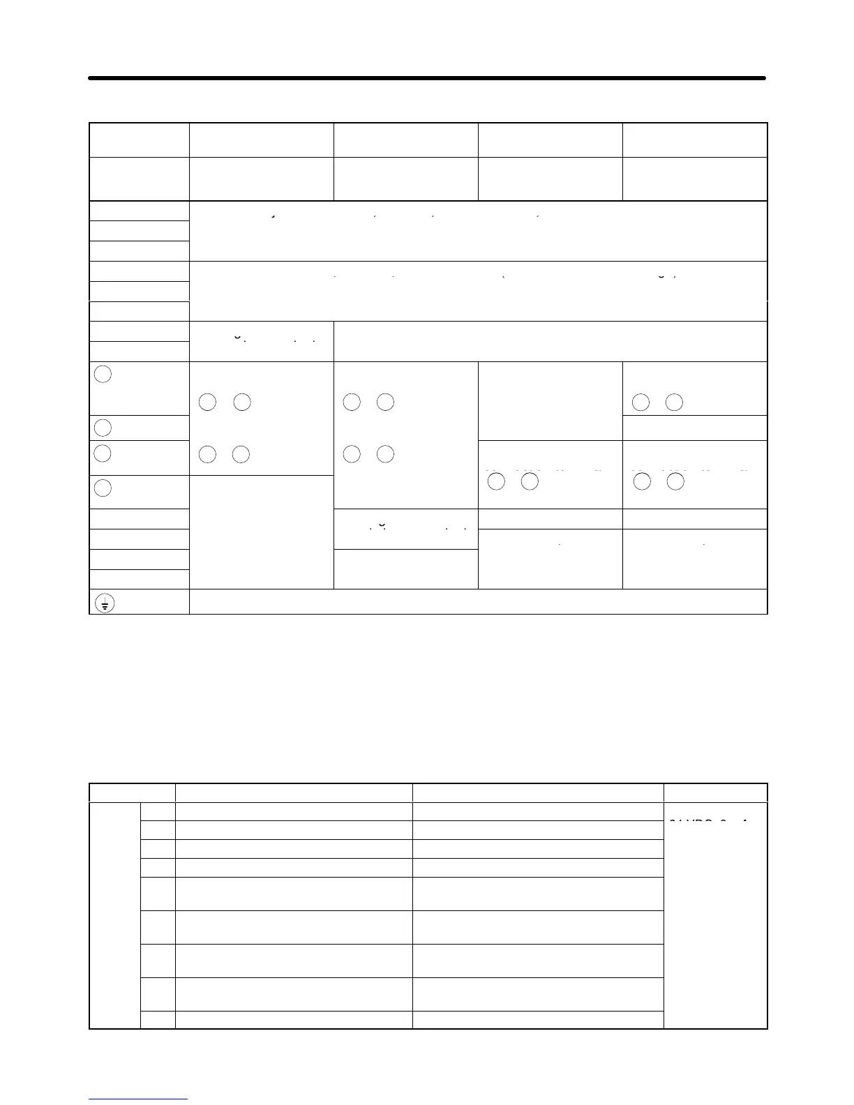
D 400-V Class
Model 3G3FV- A4004 to A4150 B4185 to B4450 B4550 to B416K-E B418K-E to
B430K-E
Maximum
applied motor
capacity
0.4 to 15 kW 18.5 to 45 kW 55 to 160 kW 185 to 300 kW
L1 (R)
Power supply input terminals, 3-phase, 380 to 460 VAC, 50/60 Hz
L2 (S)
L3 (T)
T1 (U)
Motor output terminals, 3-phase, 380 to 460 VAC (correspond to input voltage)
T2 (V)
T3 (W)
B1
Braking Resistor Unit
connection terminals
1
+
DC reactor
connection terminal
( 1- 2)
+ +
DC power supply
input terminal
( 1- )
+
–
---
DC power supply
input terminal
( 1- )
+ –
2
+
DC power supply
( 3- )
+ –
Braking Unit
connection terminal
Braking Unit
connection terminal
3
+
---
( 3- )
See note 1
+ –
s
Cooling fan power
supply input terminal
See notes 2, 3 See notes 2, 3
s200
---
s400
Ground the terminal at a resistance of less than 10 Ω.
Note 1. Don’t connect a DC power supply. Otherwise, equipment trouble may occur.
Note 2. These are the cooling fan power supply and control circuit power supply input terminals.
Note 3. When
200-V is used, input 200 to 230 V
AC from r – s200. When 400-V is used,
input 380 to
460 VAC from r – s400.
H Control Circuit Terminals for All 3G3FV Models
Symbol Name Function Signal
level
Input
1 Forward/Stop Forward at ON. Stops at OFF.
Photocoupler
2 Reverse/Stop Reverse at ON. Stops at OFF.
24 VDC, 8 mA
3 Multi-function contact input 1 Set by parameter H1-01 (external fault a).
4 Multi-function contact input 2 Set by parameter H1-02 (fault reset).
5 Multi-function contact input 3 Set by parameter H1-03 (multi-step refer-
ence 1).
6 Multi-function contact input 4 Set by parameter H1-04 (multi-step refer-
ence 2).
7 Multi-function contact input 5 Set by parameter H1-05 (jog frequency ref-
erence)
8 Multi-function contact input 6 Set by parameter H1-06 (external base-
block N.O.)
11 Sequence input common Common for 1 to 8.
Installation Chapter
2