2-20
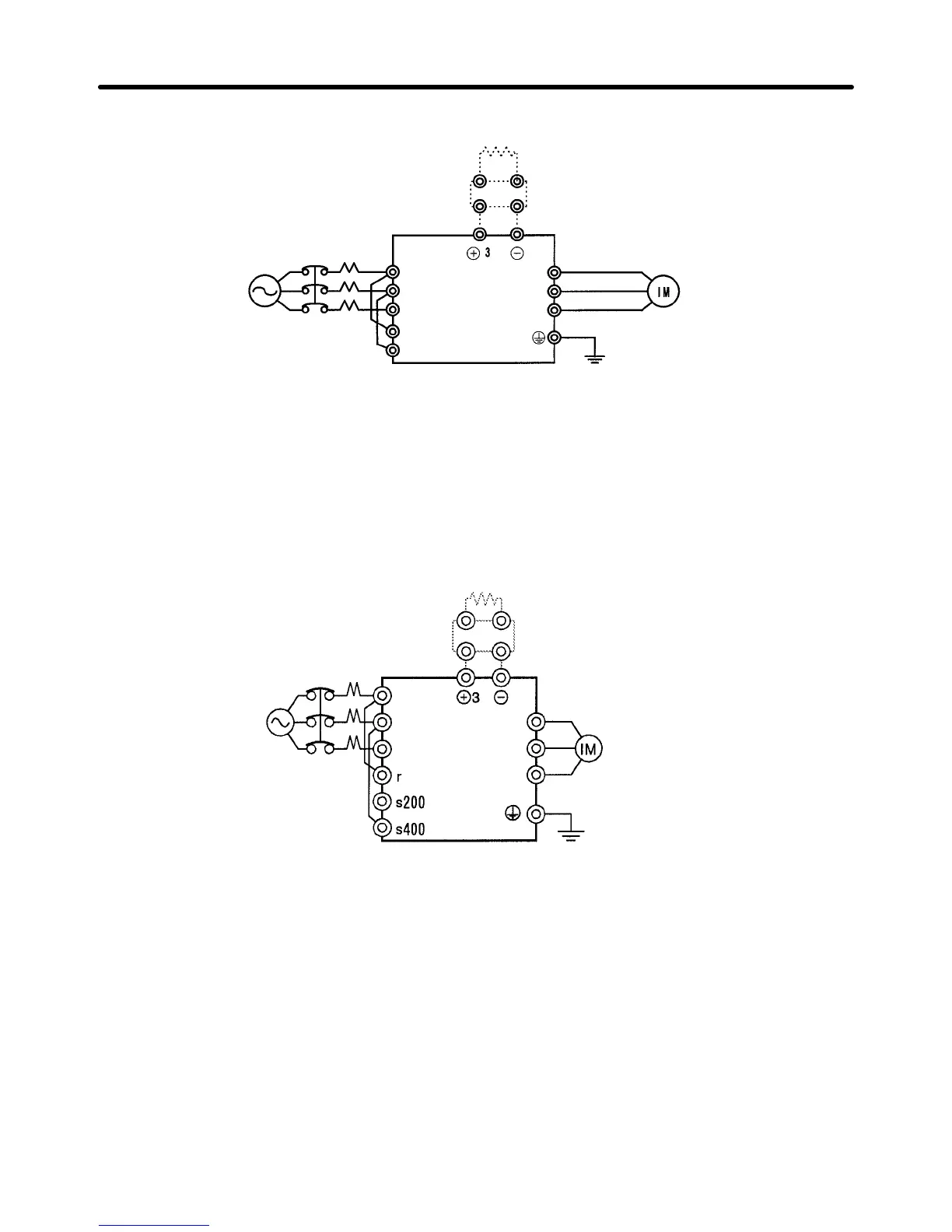
D 3G3FV-B2750-E
Note: The DC reactor is built in.
r
(See note 1)
Braking Resistor Unit (optional)
Braking Unit (optional)
L1 (R)
L2 (S)
L3 (t)
T1 (U)
T2 (V)
T3 (W)
s (See note 2)
3-phase 200 VAC
(400 VAC)
Note 1. For
200-V class, 30 to 75
kW (B2300 to B2750-E) and 400-V class, 55 to 300 kW (B4550-E to
B430K-E), input the control circuit power supply from r–s. (For others, create the control pow
-
er supply internally from the main circuit DC power supply.)
Note 2. The r–L1 (R) and s–L2 (S) terminals are short-circuited for shipping.
D 3G3FV-B4550 to B416K-E
(See
note 2)
(See note 1)
3-phase 400 VAC
Braking Resistor Unit (optional)
Braking Unit (optional)
L1 (R)
L2 (S)
L3 (T)
T1 (U)
T2 (V)
T3 (W)
Note: The DC reactor is built in.
Note 1. For
200-V class, 30 to 75
kW (B2300 to B2750-E) and 400-V class, 55 to 300 kW (B4550-E to
B430K-E), input the control circuit power supply from r–s. (For others, create the control pow
-
er supply internally from the main circuit DC power supply.)
Note 2. The r–L1 (R) and s (s400)–L2 (S) terminals are short-circuited for shipping.
Installation Chapter
2