2-22
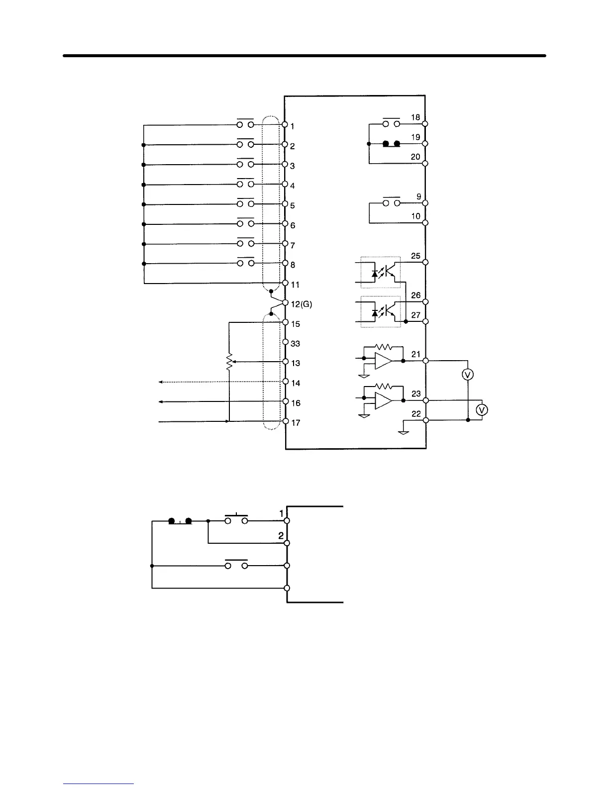
H Control Circuit Terminal Connections (All Models)
Forward/stop
Reverse/stop
Multi-function contact input 1
Multi-function contact input 2
Multi-function contact input 3
Multi-function contact input 4
Multi-function contact input 5
Multi-function contact input 6
Sequence input common
Frequency reference power supply +15 V
Frequency reference power supply –15 V
Frequency reference input (voltage)
Frequency reference input (current)
Multi-function analog input
Frequency reference input common
Fault output (NO)
Fault output (NC)
Fault output common
Multi-function contact output
Multi-function contact
output common
Multi-function output 1
Multi-function output 2
Multi-function output
common
Multi-function analog output 1
Multi-function
analog output 2
Voltmeter
Voltmeter
Multi-function analog
output common
Note Variable resistors for frequency ref-
erences must be 2 kΩ, 1/4 W min.
Wiring Example
Stop switch
(NC)
Run switch
(NO)
Run command
(Operates when the run switch is closed.)
Stop command
(Stops when the stop switch is open.)
Forward/Reverse command
(Multi-function input)
11
Sequential input common
Note Wiring methods for 3G3FV--CUE (-CE) Inverters are sometimes different.
Always check wiring
methods in the
Installation Manual
(I530 and I520).
Installation Chapter
2