2-30
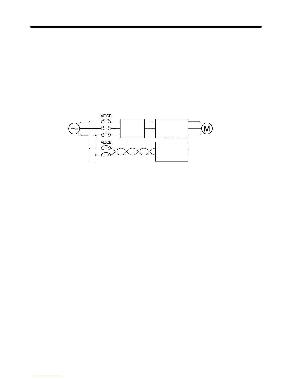
D Installing a Noise Filter on the Power Supply Side
The
Inverter
’
s outputs utilize high-speed switching, so noise may be transmitted from the Inverter to the
power line and adversely affect other devices in the vicinity. It is recommended that a Noise Filter be
installed at the Power Supply to minimize this noise transmission. Conversely, noise can also be re-
duced from the power line to the Inverter.
Wiring Example 1
Power
supply
3G3FV
SYSDRIVE
SYSMAC or
other control
device
Noise
Filter
Input Noise Filters
Simple Input Noise Filter: 3G3EV-PLNFD
Input Noise Filter: 3G3IV-PFN
EMC-conforming Input Noise Filter: 3G3FV-PFS
Note Use
a noise filter designed for Inverters. A general-purpose noise filter will be less ef
fective and
may not reduce noise.
D Calculating the Inverter Input Power Supply Capacity
The following formula can generally be used to calculate the input power supply capacity for the
Inverter. Always select an Inverter with more than sufficient capacity.
Input power supply capacity [kVA] =
Motor output [kW]/(Motor efficiency x Inverter efficiency x Inverter input power factor)
Normal
motor ef
ficiency = 0.8, Normal inverter
ef
ficiency = 0.9, Inverter input power factor = 0.65 to 0.9
Note The
Inverter
’
s input power factor will vary with the impedance of the power supply facilities. Use
0.9 when using an AC reactor and 0.65 when not using an AC reactor.
For
the input current, divide the input power supply capacity
by the input voltage. Assuming the Invert
-
er’s resistance to overloads to be 150%, the calculated value can be multiplied by 1.5.
Example for 3-phase 200 V: 1.5 x input power supply capacity/(p 3 x 200 V)
Example for single-phase 200 V: 1.5 x input power supply capacity/200 V
H Wiring on the Output Side of Main Circuit
D Connecting the Terminal Block to the Load
Connect output terminals T1 (U), T2 (V), and T3 (W) to motor lead wires T1 (U), T2 (V), and T3 (W),
respectively.
Check that the motor rotates forward with the
forward command. Switch over any two of
the output terminals to each other and reconnect if the motor rotates in reverse with the forward com
-
mand.
D Never Connect a Power Supply to Output Terminals
Never
connect a power supply to output terminals T1 (U), T2 (V), and T3 (W). If voltage is applied to the
output terminals, the internal circuit of the Inverter will be damaged.
Installation Chapter
2