EasyManuals Logo

Omron SYSDRIVE 3G3MV SERIES User Manual

Omron SYSDRIVE 3G3MV SERIES
344 pages
To Next Page IconTo Next Page
To Previous Page IconTo Previous Page
Page #214 background imageLoading...
Page #214 background image
7-24
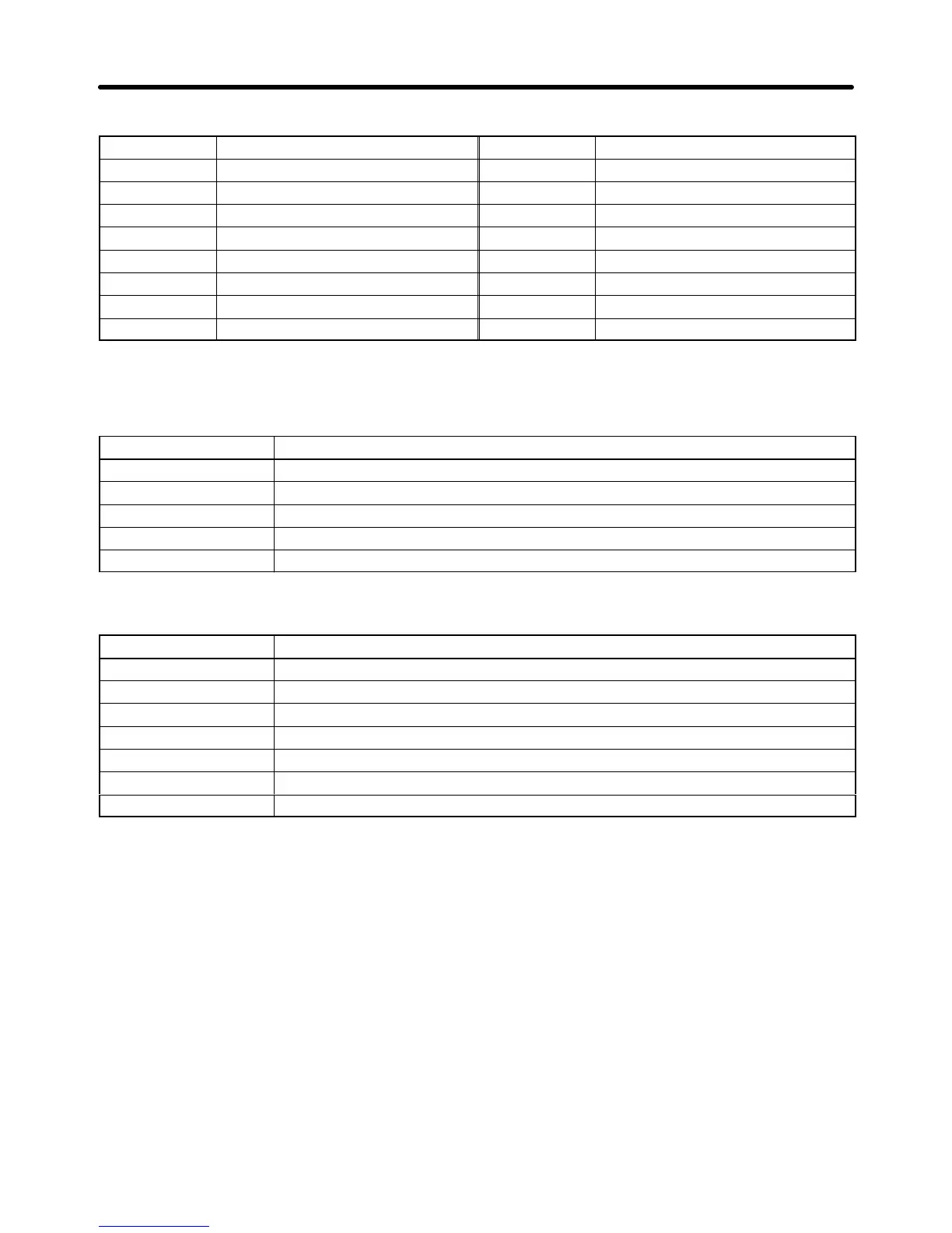
D Fault Status 1 (Register 0021 Hex)
Bit No. Function Bit No. Function
0 OC 8
Fj
1 OV 9 OL1
2 OL2 10 OL3
3 OH 11 Not used.
4 Not used. 12 UV1
5 Not used. 13 UV2
6 FBL 14 CE
7
EFj, STP
15 OPR
Note When a fault results, the corresponding bit will be set to 1.
D Data Link Status (Register 0022 Hex)
Bit No. Function
0 Data writing (1: Writing)
1 to 2 Not used.
3 Upper and lower limit error (1: Error): Outside set range
4
Verify error (1: Error): Same as OPEj.
5 to 15 Not used.
D Fault Status 2 (Register 0029 Hex)
Bit No. Function
0 SC
1 GF
2 PF
3 LF
4 RH
5 RR
6 to 15 Not used.
Communications Chapter 7

Table of Contents

Questions and Answers:

Question and Answer IconNeed help?

Do you have a question about the Omron SYSDRIVE 3G3MV SERIES and is the answer not in the manual?

Omron SYSDRIVE 3G3MV SERIES Specifications

General IconGeneral
ModelSYSDRIVE 3G3MV SERIES
CategoryInverter
Input Frequency50/60 Hz
Output Frequency0.1 to 400 Hz
Cooling MethodForced Air Cooling
Input Voltage200 to 240 VAC, 380 to 480 VAC
Horsepower Range0.1 to 15 HP
Power Range0.1 to 11 kW
Overload Capacity150% for 60 seconds
Braking UnitBuilt-in
Protection FunctionsOvercurrent, Overvoltage, Undervoltage, Overheat
CommunicationRS-485
Ambient Temperature-10 to 50°C
Storage Temperature-20 to 65°C
Humidity5 to 95% RH (non-condensing)
Vibration5.9 m/s² or less
Voltage Class200V, 400V

Related product manuals