10-32
Param-
eter
No.
Regis-
ter No.
(Hex)
Name Description Set-
ting
range
Unit
of
set-
ting
Default
setting
Changes
during
opera-
tion
Ref-
er-
ence
page
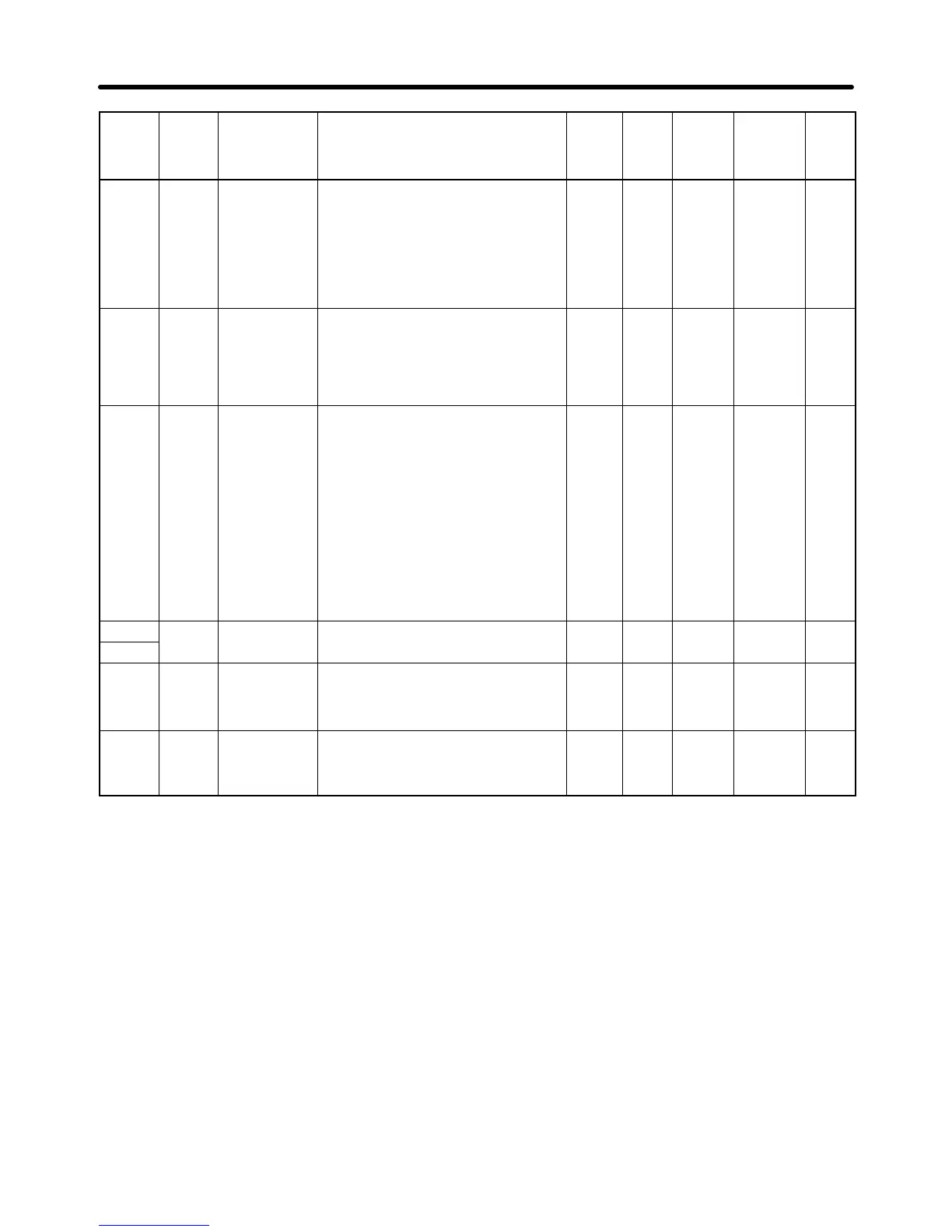
n168 01A6 Output open-
phase detec-
tion level
(See note 1.)
Sets as a percentage the current for
detecting an output open phase, tak-
ing the Inverter’s rated output current
as 100%.
If “0” is set, the output open-phase
detection function will be disabled.
Recommended setting: 5 (%)
0 to
100
1 % 0 No 6-47
n169 01A6 Output open-
phase detec-
tion time (See
note 1.)
Sets the output open-phase detection
time in units of seconds.
If “0” is set, the output open-phase
detection function will be disabled.
Recommended setting: 0.2 (s)
0.0 to
2.0
0.1 s 0.0 No 6-47
n170 01AA Enter Com-
mand Opera-
tion Selection
Select the treatment of the Enter
command for momentay power inter-
ruptions.
0: Accept Enter command only when
operation is stopped.
1: Accept Enter command at any
time.
* Changed parameters are enabled
even if the Enter command is not
sent, but the changes will be lost if
power is reset if the Enter com-
mand has not been sent.
0 to 1 1 0 No 7-18
n171
--- Not used --- --- --- --- --- ---
n172
n173 01AD Proportional
Gain for DC
Control
Normally use this parameter at the
default setting.
1 to
999
1
(0.001)
83
(0.083)
10 (See
note 2.)
No ---
n174 01AE Integral Time
Constant for
DC Control
Normally use this parameter at the
default setting.
1 to
250
1
(4 ms)
0
(100 ms)
10 (See
note 2.)
No ---
Note 1. Available for 5.5-kW and 7.5-kW Inverters only.
Note 2. These parameters are available on 200-V/400-V, 4.0-kW (or less) Inverters (software version
VSP010024 or higher) or 5.5-kW/7.5-kW Inverters (VSP010104 or higher).
List of Parameters Chapter 10

 Loading...


