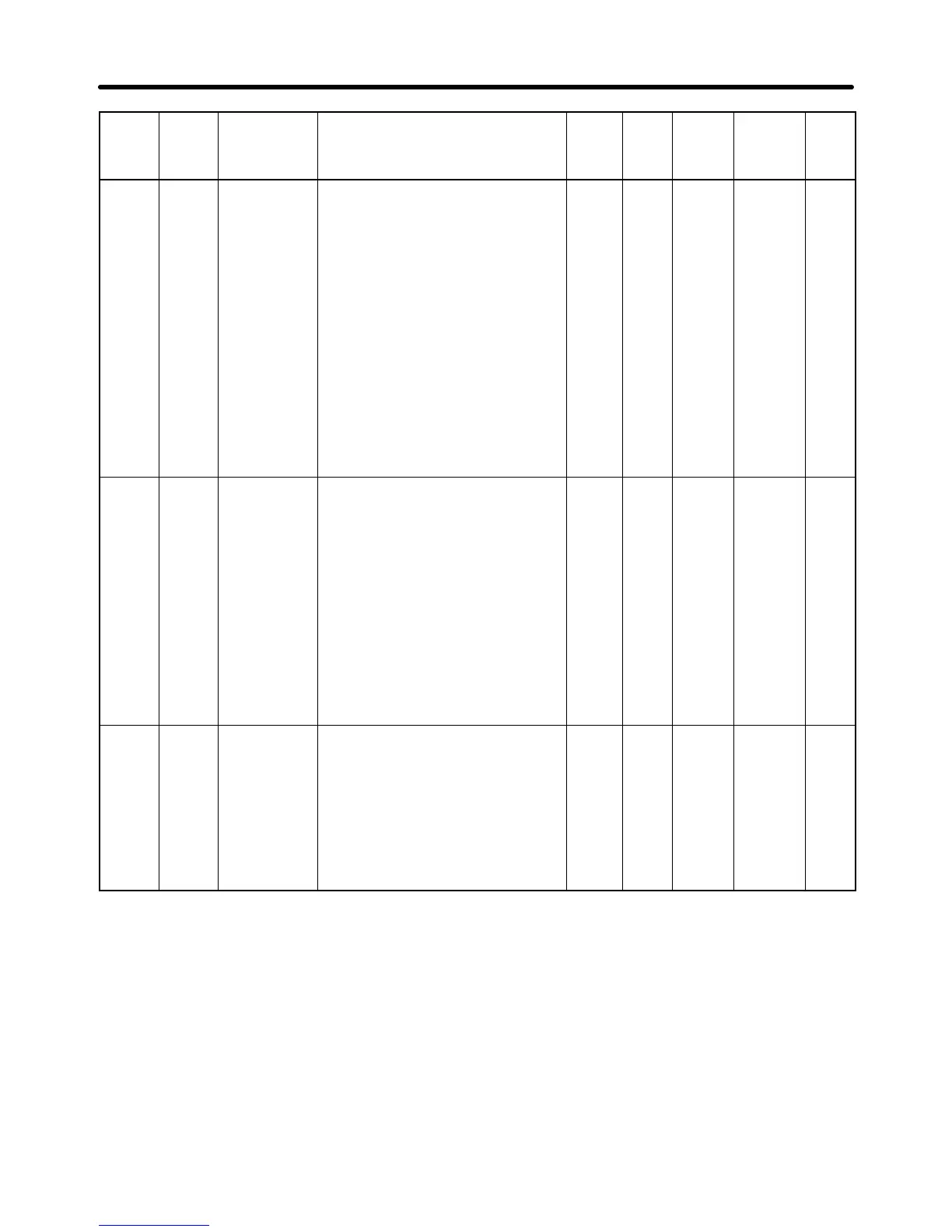
10-33
Param-
eter
No.
Regis-
ter No.
(Hex)
Name Description Set-
ting
range
Unit
of
set-
ting
Default
setting
Changes
during
opera-
tion
Ref-
er-
ence
page
n175 01AF Low-speed
carrier fre-
quency re-
duction selec-
tion
This function automatically reduces
the carrier frequency to 2.5 kHz if the
output frequency is 5 kHz or less, and
the output current is 110% or greater
than the rated Inverter current. Nor-
mally this setting is not necessary.
This function improves the overload
capacity at low frequencies.
0: Disables low-speed carrier fre-
quency reduction.
1: Enables low-speed carrier frequen-
cy reduction.
* Normally, it is not necessary to
change the default setting.
* This function is enabled if n080
(carrier frequency) is set to 2, 3, or
4.
0, 1 1 0 (See
note.)
No 6-24
n176 01B0 Parameter
copy and
verify function
selection
Selects the function to read, copy,
and verify the parameter between the
memory of the Inverter and that of the
Digital Operator.
rdy: Ready to accept the next com-
mand.
rEd: Reads the Inverter parameter.
Cpy: Copies the parameter to the
Inverter.
vFy: Verifies the Inverter parameter.
vA: Checks the Inverter capacity
display.
Sno: Checks the software number.
rdy to
Sno
--- rdy No 3-10
n177 01B1 Parameter
read prohibit
selection
Select the copy-prohibit function.
Set this parameter to store the data in
the EEPROM of the Digital Operator.
0: Read prohibited for Inverter param-
eters (data cannot be stored in
EEPROM).
1: Read possible for Inverter parame-
ters (data can be stored in
EEPROM).
0, 1 1 0 No 3-17
Note The default setting for 5.5-kW and 7.5-kW Inverters is “1.”
List of Parameters Chapter 10

 Loading...


