Prepare to Remove an SPP (SPARC M7-16)
Prepare to Remove an SPP (SPARC M7-16)
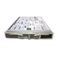
SPARC M7-16 servers have two SPPs in each CMIOU chassis and two SPs in the switch
chassis. SPPs have two service processor modules each. SPs have one SPM each. This
procedure explains how to remove an SPP.
For information about preparing SPs in the switch chassis for removal, see “Prepare to Remove
an SP” on page 125.
Note - If you issue the prepare_to_remove command for an SPM, you must also prepare
the SPP for removal. You must then return the SPP to service for the SPM to restart. This
automatically happens when an SPP is physically removed and installed into the slot, but if you
do not physically install an SPP into the slot, you must issue the return_to_service command
for the SPP. See “Return a Component to Service” on page 75.
To achieve redundancy, each SPM (SPM0 and SPM1) on an SPP is assigned to a different
DCU. SPM0 on each SPP manages one DCU in the CMIOU chassis, while SPM1 on each SPP
manages the other DCU in the chassis.
Object Managed by SPM
Pair
SPM or SPM Pair
SP0
/SYS/SP0/SPM0
SP1
/SYS/SP1/SPM0
DCU0
/SYS/SPP0/SPM0
/SYS/SPP1/SPM0
DCU1
/SYS/SPP0/SPM1
/SYS/SPP1/SPM1
DCU2
/SYS/SPP2/SPM0
/SYS/SPP3/SPM0
DCU3
/SYS/SPP2/SPM1
/SYS/SPP3/SPM1
Before you remove an SPP, you must ensure that neither of the SPMs on the SPP are the DCU
SPP (the SPP that manages DCU activity).
1.
Determine which SPP requires service.
See “Identify Faulted Components” on page 36 and “SP General Status LEDs” on page 120.
Servicing SPs 129
 Loading...
