8 Monitoring SpO2
168
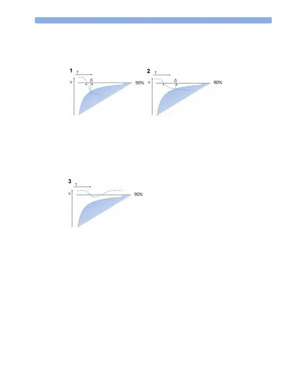
Examples
In the examples, the SpO
2
low alarm limit is set to 90%, and the Smart Alarm Delay is configured on.
The measured SpO
2
signal is represented by the dotted curve. The vertical axis (V) shows the change
in the SpO
2
value and the horizontal axis (T) shows the time.
In example 1, the SpO
2
value is dropping quickly and goes below the low alarm limit at the point
marked a. At the point marked b it also crosses into the shaded area which represents the Smart Alarm
Delay criteria - the low limit alarm is announced. The delay between the limit being crossed and the
alarm being announced, the distance between a and b, is short.
In example 2, the SpO
2
value is dropping more slowly and goes below the low alarm limit at the point
marked c. At the point marked d it also crosses into the shaded area which represents the Smart Alarm
Delay criteria - the low limit alarm is announced. The delay between the limit being crossed and the
alarm being announced, the distance between c and d, is this time longer.
In example 3, the SpO
2
value drops slowly below the low alarm limit and after a short time increases
again above the limit. As the value never crosses into the shaded area which represents the Smart
Alarm Delay criteria, no alarm is announced.
However, if a limit is exceeded by a small amount for a very long time, an alarm will be announced. For
this case there is a maximum delay time after which an alarm will always be announced.
Configuration
To accommodate different levels of patient stability, there are three different Smart Alarm Delay
settings:
Short, Medium and Long, which correspond to three different sets of criteria (three different
shaded areas). The appropriate setting for the treatment area where the monitor is to be used is
decided during monitor configuration. The
Short setting ensures a quick response to changing
conditions for less stable patients. The
Medium and Long settings extend the delay to avoid
unnecessary alarms for more stable patients. For detailed numeric information about the different
settings, see the SpO
2
section in the Specifications chapter. For background information as a basis for
the decision for a specific setting, see the Configuration Guide.
 Loading...