LIFEPAK 15 Monitor/Defibrillator
Service Manual
Replacement Procedures
System (A01)/Therapy (A04) PCB Assembly Replacement
Section Menu Section Contents Procedures Back Index
233
8
Removing the System (A01)/Therapy (A04) PCB Assembly
To remove the system/therapy PCBs as a single unit from the rear case: 9 steps, (Page 1 of 6)
1. Disassemble the case as described in Disassembling the Case
(p. 181).
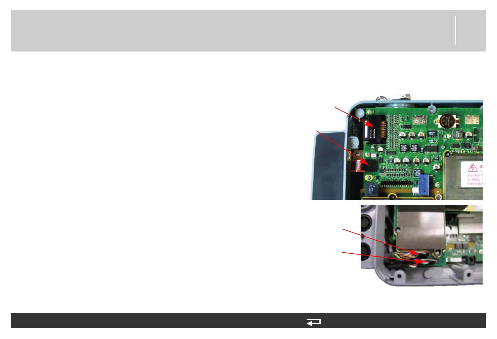
2. Disconnect the connectors on the system PCB as follows:
~ J1 – Press the connector locking tabs and disconnect the
power/system PCB cable (W01, 3207692-000).
~ J2 – (The system/interface PCB cable was disconnected
during case disassembly (Disassembling the Case (p. 181)).
~ J4 – Disconnect the USB flex connector (W14, 3206966-
001).
~ J6 – Disconnect the ECG connector cable (W7, 3007991-
007).
~ (If present) J7 – Disconnect the IP connector of the IP wire
harness (W33, 3200466-01).
~ (If present) J7 – Disconnect the temperature connector of
the temperature cable (W35, 3303936-001).
J1 power/
system PCB
cable
J4 USB flex
connector
J6 ECG cable
J7 IP/Temp cable
(if present)
Figure 8.35—System
PCB connectors