LIFEPAK 15 Monitor/Defibrillator
Service Manual
Replacement Procedures
Installing the System (A01)/Therapy (A04) PCB Assembly
Section Menu Section Contents Procedures Back Index
245
8
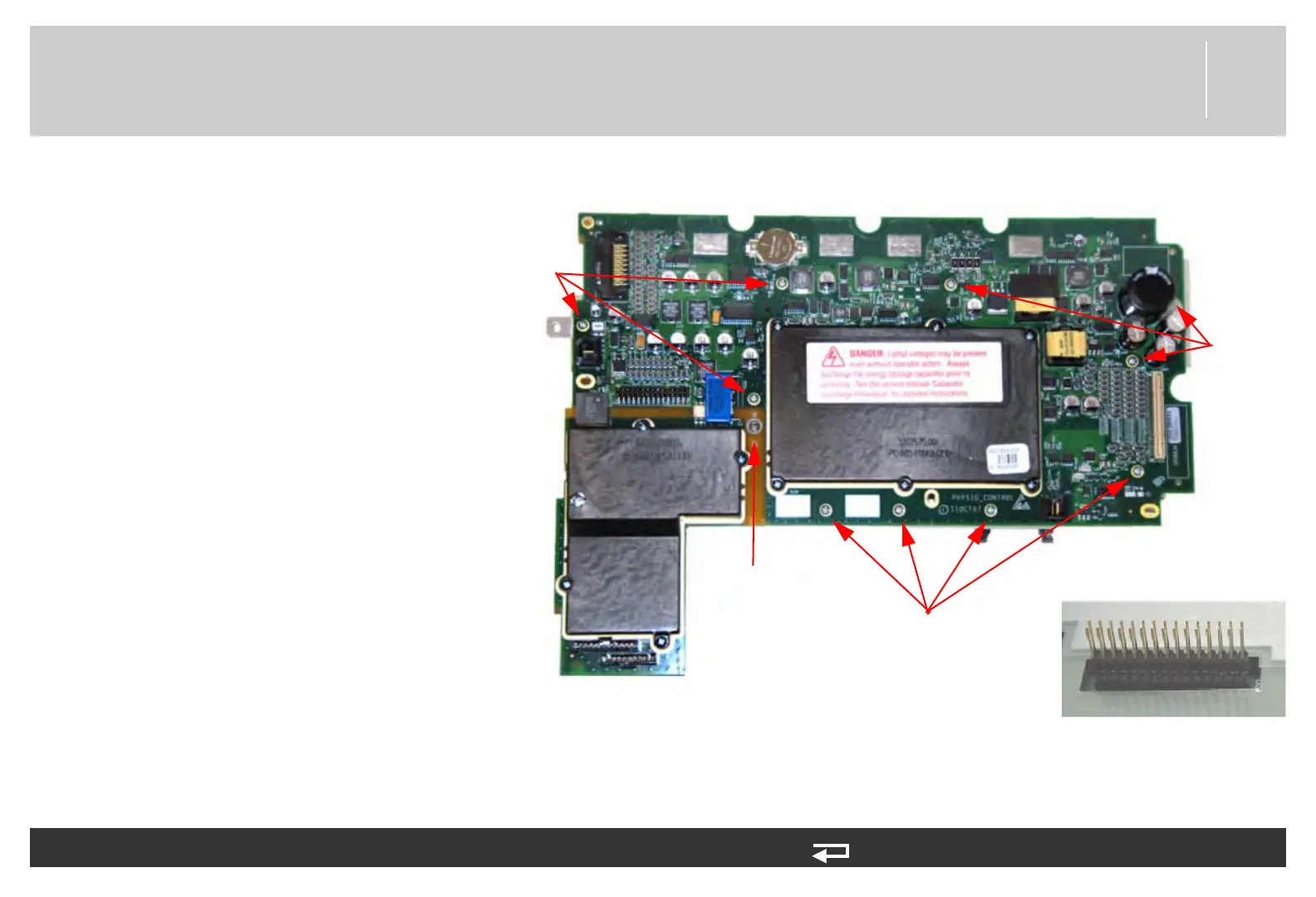
4. Place the system/therapy PCB
assembly with the system PCB
(3206834) face up on your work
surface. Remove the ten screws
(202253-761). Discard the
screws.
5. Remove the mounting screw
(202253-550) from the insert
hex nut (3011629-00). Remove
the screw, spacer and insert hex
nut from the assembly. Discard
the screw.
6. Gently lift the system PCB up
and away from the therapy PCB.
The two PCBs are linked by the
30-pin header, which is a direct-
connection contact assembly.
To separate the system PCB (A01) from the therapy PCB (A04): (Continued) 6 steps, (Page 2 of 2)
screw locations
(4 places)
screw
locations
(3 places)
screw
locations
(3 places)
spacer and
screw
30-pin header connector
Figure 8.46—System/therapy PCB screw locations