LIFEPAK 15 Monitor/Defibrillator
Service Manual
Replacement Procedures
Installing the System (A01)/Therapy (A04) PCB Assembly
Section Menu Section Contents Procedures Back Index
249
8
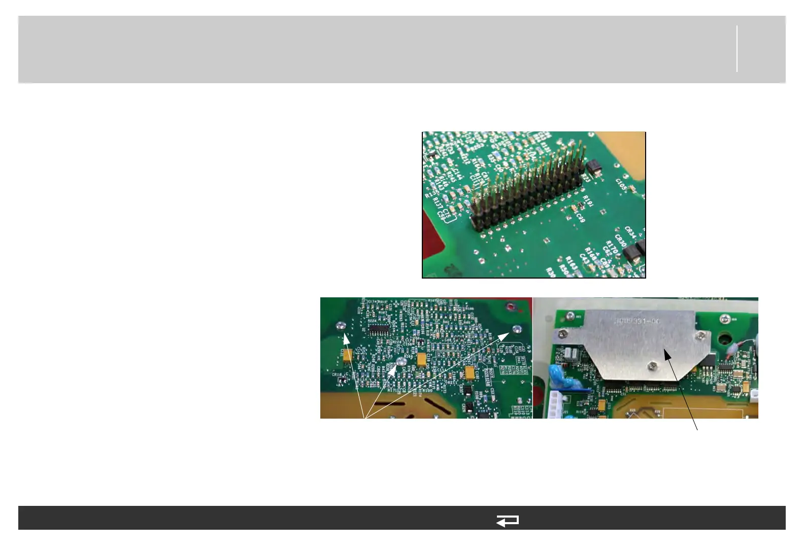
6. Gently lift the therapy PCB up
and away from the system PCB.
The two PCBs are linked by the
30-pin header, which is a direct-
connection contact assembly.
7. Remove the 30-pin header
assembly from the therapy board
(3009878-002).
8. Remove the three retaining
screws (202253-761) from the
EMI shield (3009331-00) on the
therapy board. Discard the
screws.
9. Remove the EMI shield.
To remove the therapy PCB (A04): (Continued) 9 steps, (Page 3 of 3)
Figure 8.49—30-pin header (therapy PCB side)
Figure 8.49—Therapy EMI shield and screw locations
screws
(3 places)
EMI shield