LIFEPAK 15 Monitor/Defibrillator
Service Manual
Replacement Procedures
Installing the System (A01)/Therapy (A04) PCB Assembly
Section Menu Section Contents Procedures Back Index
248
8
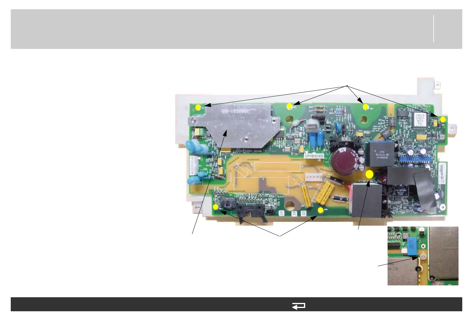
4. Place the system/therapy PCB
assembly with the therapy PCB
face up. Remove the six screws
(202253-761). Discard the
screws.
5. Remove the mounting screw
(202253-550) and spacer
(3011630-00) from the insert
nut (3011629-00). Set aside
spacer and insert nut. Discard the
screw (202253-550).
To remove the therapy PCB (A04): (Continued) 9 steps, (Page 2 of 3)
screw locations
(2 places)
screw locations
(4 places)
Inset hex nut, therapy
PCB side
screw and spacer,
system PCB side
Figure 8.48—Therapy PCB screw locations
EMI shield