LIFEPAK 15 Monitor/Defibrillator
Service Manual
Replacement Procedures
SpO2 PCB (A16) Replacement
Section Menu Section Contents Procedures Back Index
275
8
Removing the SpO2 PCB (A16)
To remove the SpO2 PCB from the rear case (see Figure 9.21 on p. 413): 13 steps, (Page 1 of 5)
1. Disassemble the case as described in
Disassembling the Case (p. 181).
2. Remove the system/therapy PCB assembly as
described in System (A01)/Therapy (A04) PCB
Assembly Replacement (p. 232).
3. Remove the OEM shield (3208298-000).
4. Disconnect the power/contact PCB cable (W05)
from the power board J12.
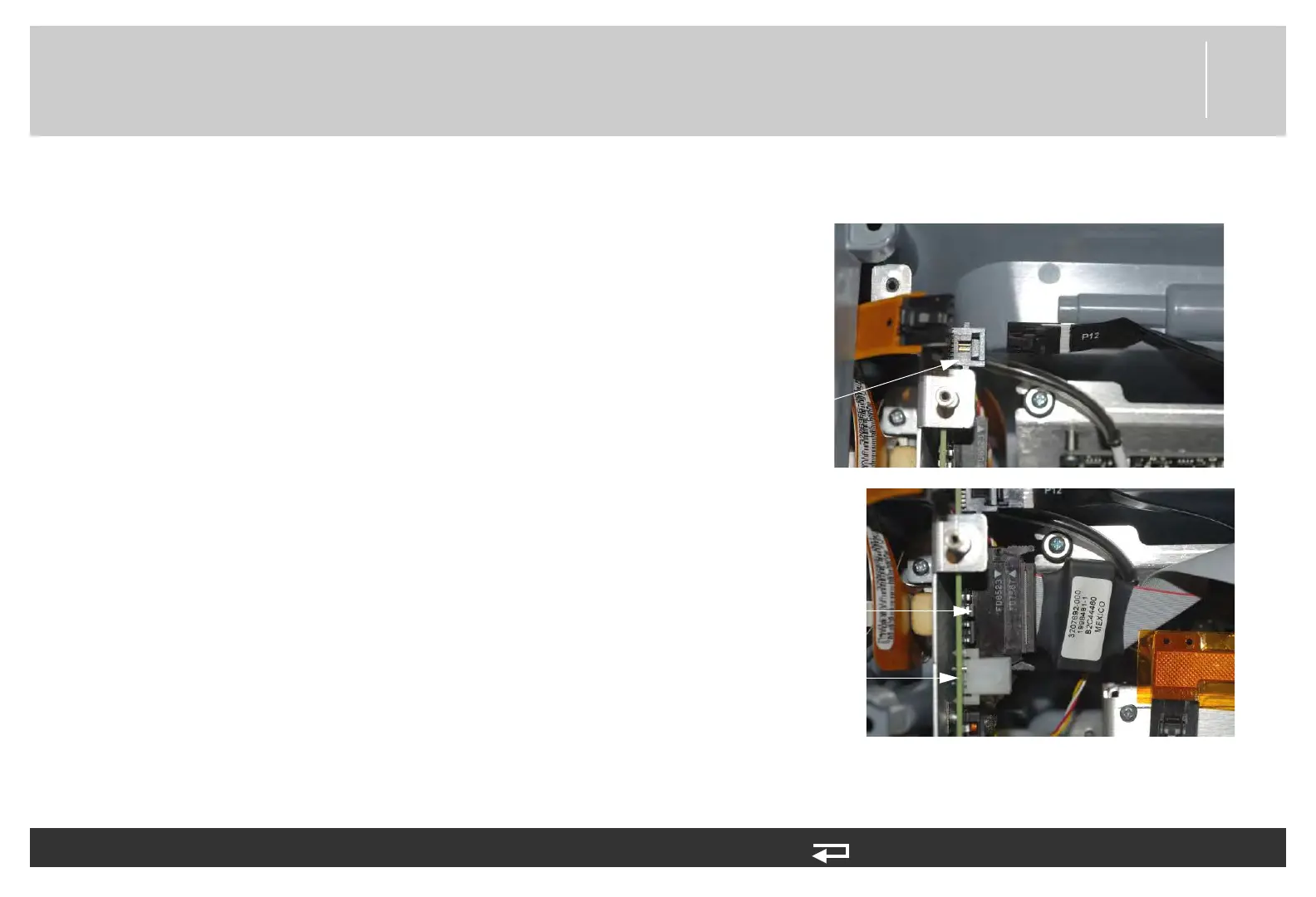
5. Remove power/system cable (W01) from the power
board J17.
6. Remove the power/therapy cable (W02) (3009726-
05) from J8 on the power PCB.
J17
connection
J8
connection
Figure 8.67—Power/system PCB connections