LIFEPAK 15 Monitor/Defibrillator
Service Manual
Replacement Procedures
Biphasic Module (A22)/Inductive Resistor (A14) Replacement
Section Menu Section Contents Procedures Back Index
299
8
Removing the Biphasic Module (A22)/Inductive Resistor (A14)
To remove the biphasic module and/or the inductive resistor from the rear case (refer to Inside Rear Case Diagrams (p. 228)):
12 steps, (Page 1 of 3)
1. Disassemble the case as described in Disassembling the Case (p. 181).
2. Remove the system/therapy PCB assembly as described in System (A01)/
Therapy (A04) PCB Assembly Replacement (p. 232).
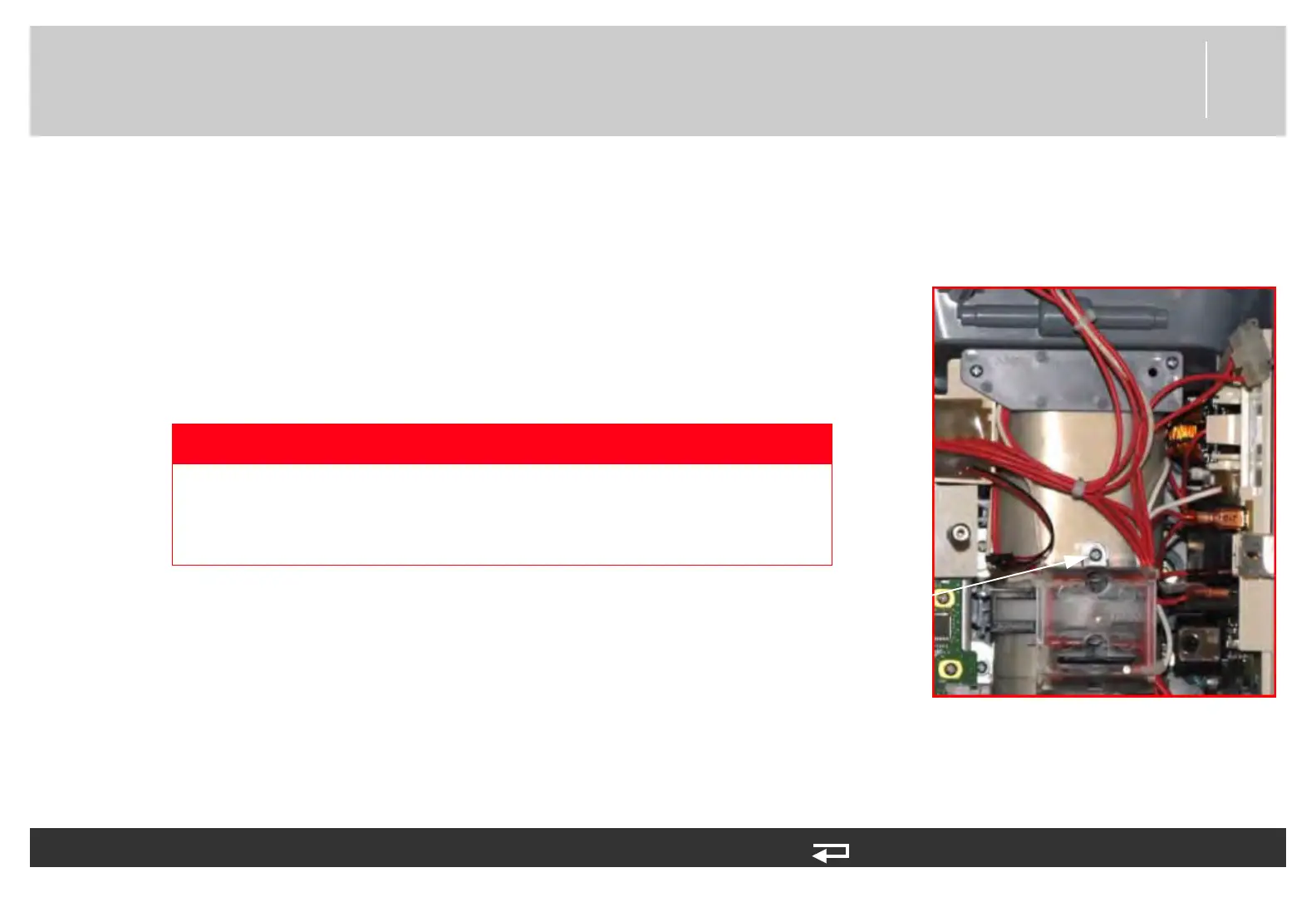
3. Remove the screw (202253-761) securing the clear, plastic, high-voltage
shield (3010593-00) to the interconnect bracket (A17). Discard the screw.
4. Cut the two cable ties on the right side of the interconnect bracket.
5. Disconnect the three biphasic module spade terminal connectors from the
interconnect bracket (A17 - pin 3, pin 6, and pin 9). Needle nose pliers
may be used to assist in disconnection.
cover screw
Figure 8.94—Interconnect bracket screw locations
DANGER
SHOCK HAZARD Lethal voltages may be present even without
operator action. Always discharge the energy storage capacitor
prior to servicing. See the service manual “Capacitor Discharging
Procedure (p. 178)” for detailed instructions.