3
Figure 4 - TESTING PINION MOVEMENT AND PULL-
IN WINDINGS (GROUND-FLOAT TYPE)
For the starter switch coils, refer to the
switch circuit diagrams for the ground-wire
type (ground-float type) shown in figures 5.
Figure 5 - SOLENOID CIRCUIT (GROUND-FLOAT
TYPE)
If the pinion is performing properly, follow
the procedure as described below to inspect
the H-coil in the starter solenoid.
Remove the M-terminal nut as described in
figure 6 and keep the lead wire end in
contact with the M-terminal. Apply voltage
between the S-terminal and the ground to let
the pinion advance forward. Immediately
after that, separate the lead wire from the M-
terminal and check if the pinion stays in the
advanced forward position while voltage is
applied to the H-coil only. If the pinion
returns, replace the starter. The H-coil is
assumed to be layer-shorted.
* M-terminal nut tightening torque: 20 to 30
N⋅m
Figure 6 - TESTING HOLD-IN WINDINGS (GROUND-
FLOAT TYPE)
Below are the resistance values for the P-
and H-coils for reference.
Coil Resistance (reference)
P-coil
0.072ohm at 68° F
H-coil
1.300 ohm at 68° F
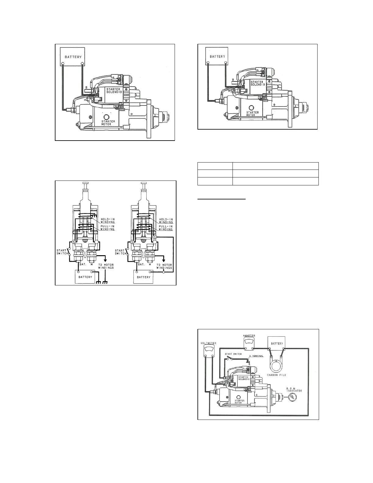
2.5.2 No-load test
The no-load test makes it easy to inspect
the starter for functional failure without
disassembling. This test can also identify an
open/short circuit that is difficult to check
when disassembled.
As shown in figure 7, connect the starter,
fully charged battery, ammeter, and
voltmeter. If possible, connect a resistor
suitable for voltage control in parallel with
the battery. In addition, use an rpm indicator
to measure the revolution speed of the
output shaft.
Note:
Attention should be given to the
output shaft which advances forward to
approximately 0.8" (20 mm) and rotates at
that position when the starter is operated.
Figure 7 - NO-LOAD TEST CIRCUIT (BODY-
GROUND TYPE)